
Lesson 13
Two-ports
Find the two-port equivalent of a network. Learn how to include two-ports in your circuit using the z, y, h, g, a and b elements. Calculate gains with the gain mini-tool.
Last updated 2026-08-29
A two-port is a network you have stopped caring about the inside of. What is left is four numbers relating the voltage and current at one pair of terminals to the voltage and current at the other. Symbulator will find those four numbers for you, and will also take them as an element in a larger circuit.
13.1Find two-port equivalents
Set Type of analysis to Find equivalent and Type of equivalent to Two-port parameters. It takes the network and the two top nodes of the pair of terminals you want to reduce. The two bottom nodes are ground unless you say otherwise: a port whose lower terminal is not ground is written as a pair, [top,bottom], in its node box — the same spelling a two-port element uses for its own ports. A side of the circuit with no path to node 0 at all, the far side of a block or a whole network with no ground, is measured against a reference of its own, and the answers say which node that is.
There are six kinds of parameters — z, y, h, g, a and b — and you choose which you want.
AS7's Example 19.1
Open in app ↗Open in split view
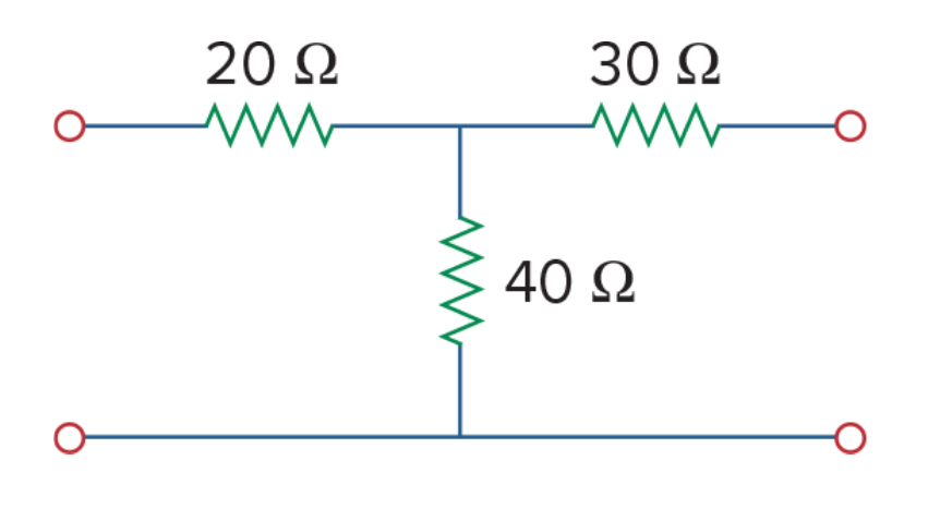
Determine the z parameters for the circuit.
AS7's Example 19.1
Solution
First describe the network, exactly as you would describe any circuit:
r1,1,2,20
r2,2,0,40
r3,2,3,30
Find equivalent, then Two-port parameters, with Parameters set to z — impedance and 1 and 3 in the two node boxes. In DC.
There is no name to invent: the four come back as z11, z12, z21 and z22.
Results gives z11 = 60 Ω, z12 = 40 Ω, z21 = 40 Ω and z22 = 70 Ω.
Correct.
13.2Use two-ports as elements
A two-port can be an element in a bigger circuit. Its description is three fields: a name whose first letter says which kind it is, then the top left node and the top right node. Both bottom nodes are ground, always — which is why neither top node may be 0, and the two may not be the same node; Symbulator stops with a message if they are.
z,1,2That is a z-type two-port between nodes 1 and 2. An optional fourth term carries its four parameters — see below.
All four terminals. When a bottom node is not ground, write each port as a bracketed pair, top node then bottom node:
z,[1,3],[2,4]That is port 1 between nodes 1 and 3 and port 2 between nodes 2 and 4; the parameter term, when there is one, follows as before, z,[1,3],[2,4],[40,20j,30j,50]. Either node of a pair may be 0, so z,[1,0],[2,0] is the two-node form written out. A two-port conducts nothing from one port to the other, so a side of the circuit with no path of its own to ground is an island: Symbulator takes the port's lower terminal as that side's own reference and says so in a note above the results. A port whose two nodes are the same is refused.
Its answers are the current entering the two-port at each of its live nodes, named with the element and the node — iz1, iz2, iz3, iz4 for the example above — shown under the element's own name in the results.
Giving it its four parameters
Three possibilities.
Give them in the description, as an optional fourth term — a list of four, in the order 11, 12, 21, 22:
z,1,2,[40,20j,30j,50]Prefer this way: the parameters travel with the circuit, into links, files and every analysis, the equivalent tools included. The entries can be numbers, SI-prefixed values or expressions.
Give them values in Define, and keep the description bare:
z11 = 40
z12 = 20j
z21 = 30j
z22 = 50
Define any subset and the rest stay symbolic.
Leave them undefined, in which case they stay symbolic and appear in the answers as z11, z12, z21 and z22. That is often what you want — the answer as a formula in the parameters. (Pinning them afterwards in Expert Mode's Add equation(s) still works too, in a plain solve, and an equation or condition there overrides the description's own values.)
What answers do you get? The current entering each port, named with the two-port and the node it sits on — for a two-port z on nodes 1 and 2, that is iz1 and iz2.
AS7's Example 19.2
Open in app ↗Open in split view
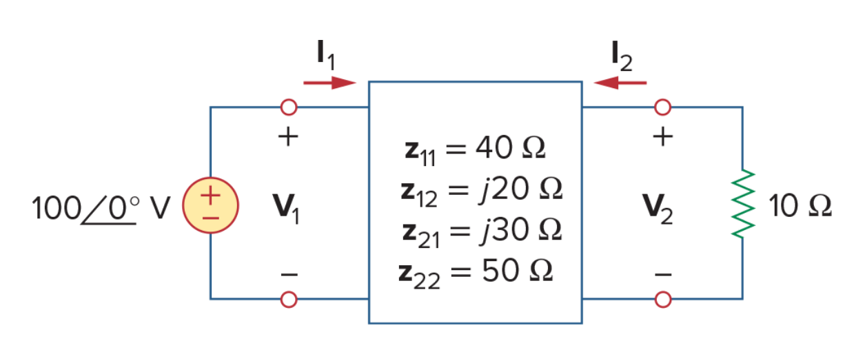
Find I1 and I2 in the circuit.
AS7's Example 19.2
Solution
e,1,0,100
z,1,2,[40,20j,30j,50]
r,2,0,10
The four parameters ride in the description's fourth term. In AC.
aa(iz1) reads 2∠0° A and aa(iz2) reads 1∠-90° A.
13.3Instructive two-port problems
AS7's Example 19.3
Open in app ↗Open in split view
Obtain the y parameters for the network.

AS7's Example 19.3
Solution
r1,1,0,4
r2,1,2,2
r3,2,0,8
Find equivalent, Two-port parameters, y — admittance, nodes 1 and 2, DC.
3/4, -1/2, -1/2, 5/8, all in S.
Correct.
AS7's Example 19.4
Open in app ↗Open in split view
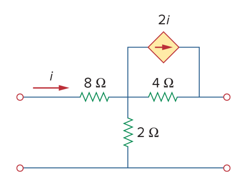
Determine the y parameters for the two-port shown. Note the dependent source.
AS7's Example 19.4
Solution
r1,1,2,8
r2,2,0,2
r3,2,3,4
j,2,3,2*ir1y, nodes 1 and 3, DC. A two-port equivalent works perfectly well around a controlled source.
3/20, -1/20, -1/4, 1/4, all in S.
Correct.
AS7's Example 19.5
Open in app ↗Open in split view
Find the hybrid parameters for the two-port network.

AS7's Example 19.5
Solution
r1,1,2,2
r2,2,0,6
r3,2,3,3
h — hybrid, nodes 1 and 3, DC.
4, 2/3, -2/3, 1/9.
Correct.
AS7's Example 19.6
Open in app ↗Open in split view
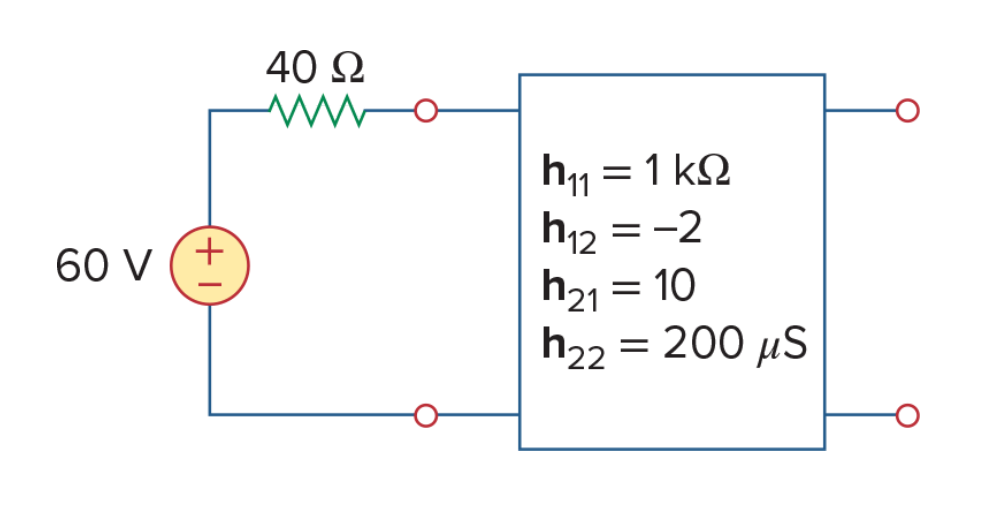
Determine the Thévenin equivalent at the output port of the circuit, whose h parameters are 1000 Ω, −2, 10 and 2×10⁻⁴ S.
AS7's Example 19.6
Solution
e,1,0,60
r,1,2,40
h,2,3,[1000,-2,10,2e-4]
Find equivalent, Thévenin / Norton, nodes 3 and 0, DC. The parameters ride in the description, so the answers come back as numbers.
Leave the fourth term off — h,2,3 alone — and the same run answers with formulas instead:
which is useful in its own right: put vth in Evaluate with the four parameters in its Conditions box, and the same number falls out.
vth comes back -29.69 V and req 51.46 Ω.
Correct.
AS7's Example 19.7
Open in app ↗Open in split view
Find the g parameters as functions of s for the circuit.
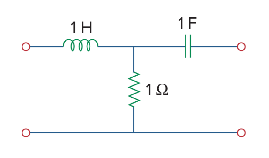
AS7's Example 19.7
Solution
l,1,2,1
r,2,0,1
c,2,3,1
g — inverse hybrid, nodes 1 and 3, and this time in FD, since the question asks for functions of s.
The four come back as
AS7's Practice Problem 19.7
Open in app ↗Open in split view
For the ladder network, determine the g parameters in the s domain.

AS7's Practice Problem 19.7
Solution
l1,1,2,1
r1,2,0,1
l2,2,3,1
r2,3,0,1g, nodes 1 and 3, FD. The four come back as
Correct.
AS7's Example 19.8
Open in app ↗Open in split view
Find the transmission parameters for the two-port network.
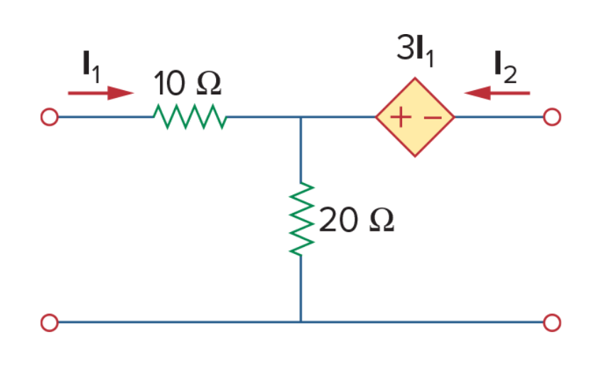
AS7's Example 19.8
Solution
r1,1,2,10
r2,2,0,20
e,2,3,3*ir1
a — transmission, nodes 1 and 3, DC.
1.765, 15.29, 0.0588, 1.176.
Correct.
13.4The gain mini-tool
Network problems ask for gains: voltage gain, current gain, power gain, and the impedance seen at the input. Symbulator has a mini-tool for that — the third in the Mini-Tools card Lesson 7 introduced: choose gain.
It wants four values — the voltage and current at the input, then the voltage and current at the output — and answers with all four figures at once.
Gain Example 1
Open in app ↗Open in split view
For the circuit, find Gv, Gi, Gp and Zin. The two-port has y parameters y11 = 0.4 S, y12 = −0.002 S, y21 = −5 S and y22 = 0.04 S.
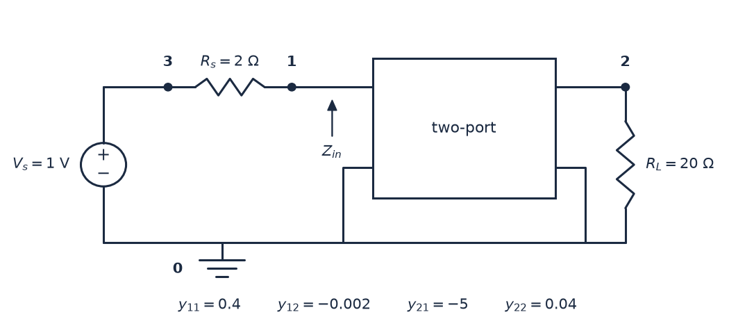
Gain Example 1
Solution
The source is 1 V because its value does not matter to a gain — it cancels. A symbolic vs would do just as well.
es,3,0,1
rs,3,1,2
rl,2,0,20
y,1,2,[0.4,-0.002,-5,0.04]
Solve in DC, then open Mini-Tools, choose gain, and give it the four:
v1iy1v2iy2The voltage gain Av is 55.56, the current gain Ai -9.615, the power gain Ap 534.2, and the input impedance Zi 3.462 Ω.
These are correct.
Gain Example 2
Open in app ↗Open in split view
Find Gv, Gi, Gp and Zin for a two-port with z parameters z11 = 4 Ω, z12 = 1.5 Ω, z21 = 10 Ω and z22 = 3 Ω, driven by a source Vs with 5 Ω in series and loaded with 2 Ω.
There is no picture of this one — the description below is the whole circuit.
Solution
The same shape as before, with z parameters instead of y.
es,3,0,1
rs,3,1,5
rl,2,0,2
z,1,2,[4,1.5,10,3]
Solve in DC, then open Mini-Tools, choose gain, and give it the four:
v1iz1v2iz2The voltage gain Av is 4, the current gain Ai -2, the power gain Ap 8, and the input impedance Zi 1 Ω.
These are correct.
An h-parameter model with a resistor under its common terminal
Open in app ↗Open in split view
A transistor stage described by its hybrid parameters, hie = 1 kΩ, hre = 2.5 × 10⁻⁴, hfe = 100 and hoe = 25 µS, is driven by a 10 mV source through a 1 kΩ resistor and loaded by 2 kΩ. Its common terminal is not grounded: a 100 Ω resistor sits between it and ground. Find the output voltage, and compare it with the same stage with the common terminal grounded.
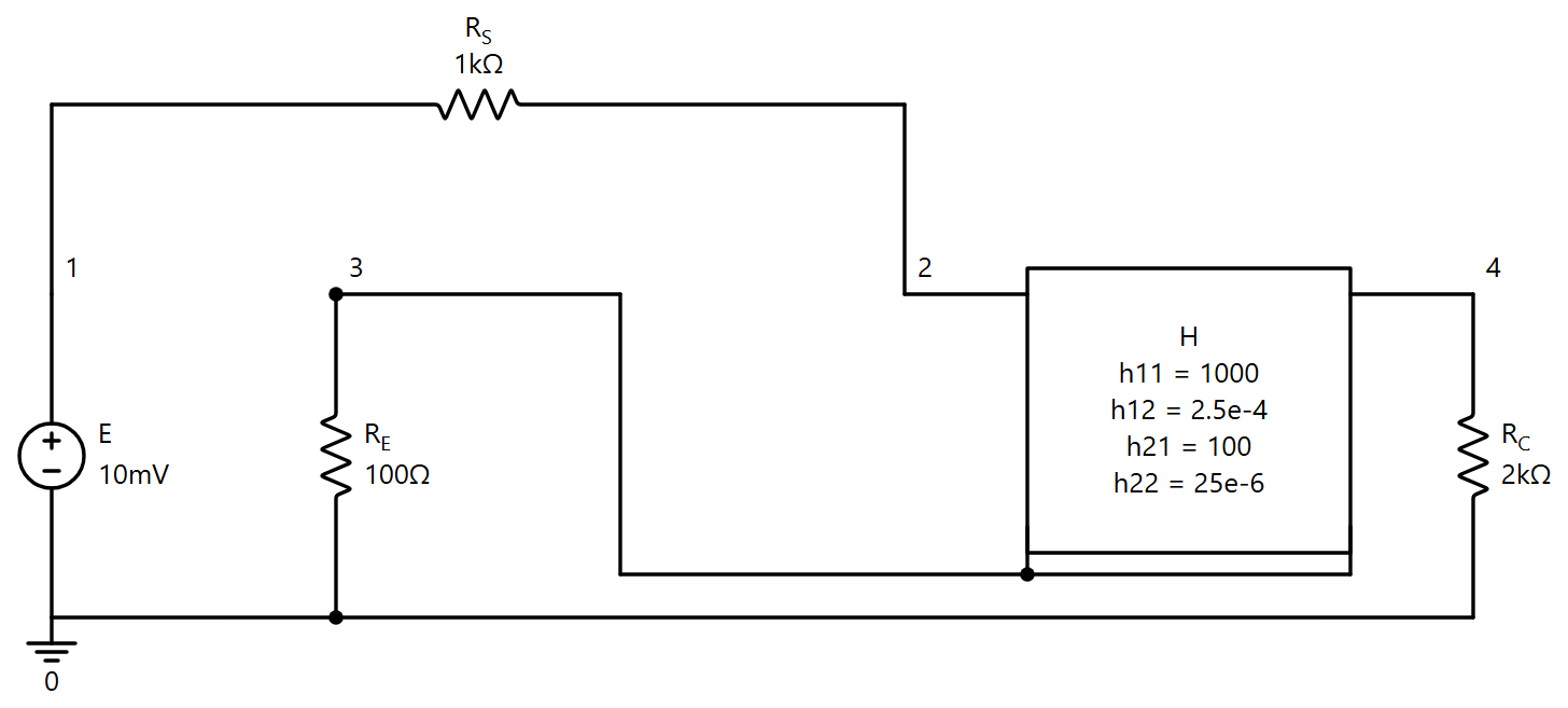
An h-parameter model with a resistor under its common terminal, drawn by Symbulator
Solution
The two-node form cannot describe this: it grounds both bottom terminals, and the whole point is the resistor under them. With the four-terminal form each port is a pair, and both pairs share node 3, the common terminal.
e,1,0,0.01
rs,1,2,1000
h,[2,3],[4,3],[1000,2.5e-4,100,25e-6]
re,3,0,100
rc,4,0,2000
DC. Results gives v4 = -0.1645 V, a voltage gain of -16.45, and under h the three currents entering the block: ih2 = 0.8657 µA at the input, ih4 = 82.25 µA at the output, and ih3 = -83.12 µA at the common terminal — the sum of the other two, leaving the block, which is the current through the 100 Ω resistor.
Ground the common terminal instead, h,2,4,[1000,2.5e-4,100,25e-6] with no re, and v4 is -0.9756 V, a gain of -97.56. The resistor under the common terminal costs a factor of six in gain, which is what emitter degeneration does.
A z-block with its second port lifted off ground
Open in app ↗Open in split view
A z-parameter block, z = [100, 10, 20, 50], is driven at its first port by a 10 V source. Its second port feeds a 200 Ω load, but the port's lower terminal is not ground: it reaches ground through a 20 Ω resistor. Find the currents into the block and the voltage at its lower terminal.
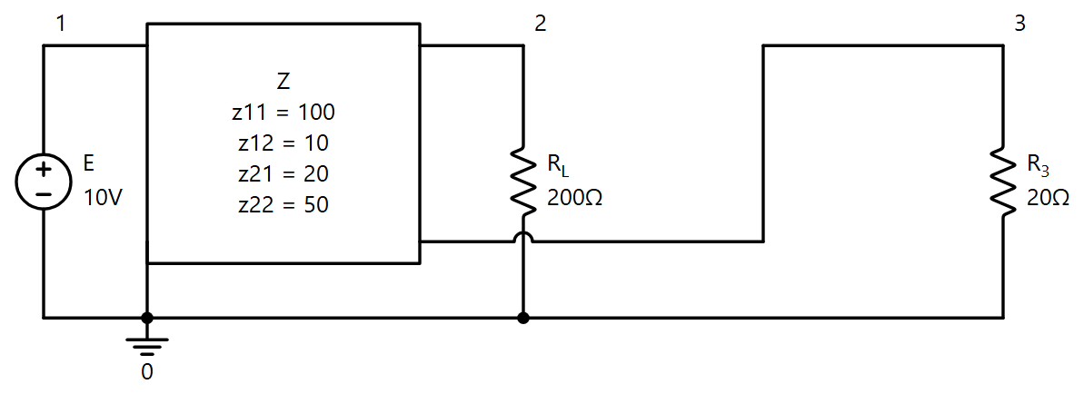
A z-block with its second port lifted off ground, drawn by Symbulator
Solution
Port 1 is the pair [1,0], grounded as before; port 2 is the pair [2,3].
e,1,0,10
z,[1,0],[2,3],[100,10,20,50]
rl,2,0,200
r3,3,0,20
DC. Results gives, under z,
and v3 is -10/67 V. The second port's current leaves the block at node 2, goes down through the load to ground, and comes back up through the 20 Ω resistor into node 3 — which is why iz2 and iz3 are equal and opposite, and why node 3 sits below ground.
Three problems from Alexander and Sadiku's Chapter 19 in which no port is grounded — the case the pair spelling exists for. In each, grounding the bottoms instead would solve a different circuit and hand back plausible, wrong numbers.
AS7's Problem 19.2
Open in app ↗Open in split view
Determine the equivalent impedance parameters of the ladder: four 1 Ω resistors in the upper rail, four in the lower, three 1 Ω rungs.

AS7's Problem 19.2, drawn by Symbulator with f as the reference the tool takes
Solution
Neither rail is ground, so each port is a pair: port 1 is [a,f], port 2 is [e,j].
r1,a,b,1
r2,b,c,1
r3,c,d,1
r4,d,e,1
r5,f,g,1
r6,g,h,1
r7,h,i,1
r8,i,j,1
r9,b,g,1
r10,c,h,1
r11,d,i,1
z — impedance, with [a,f] and [e,j] in the two node boxes. DC. Results gives z11 = z22 = 2.733 Ω and z12 = z21 = 0.06667 Ω — exactly 41/15 and 1/15. Symmetric, as the drawing is, and small in transfer: three shunt ohms bleed nearly everything to the far rail.
The network has no node 0 anywhere. The tool takes each port's lower terminal as the reference for its own measurement, which is what the definition of the parameters does. Type a and e instead, with the lower rail grounded, and the answer is 11/5 and 3/5 — the parameters of a different circuit, the lower rail's resistors shorted out.
AS7's Problem 19.19
Open in app ↗Open in split view
Determine the y parameters of the two-port in terms of s: 1 Ω in each rail, then a 1 F capacitor and a 1 H inductor side by side between the rails.

AS7's Problem 19.19, drawn by Symbulator with f as the reference the tool takes
Solution
Port 2 is the pair of junctions, [x,y]; port 1 the pair of outer ends, [a,f]. Neither is grounded.
r1,a,x,1
r2,f,y,1
c,x,y,1
l,x,y,1
y — admittance, FD. The four come back as
all in siemens. With port 2 shorted the capacitor and inductor are shorted with it, so port 1 sees the two series ohms and returns all of that current through the short; with port 1 shorted, port 2 sees the capacitor and inductor in parallel, s + 1/s, plus the two ohms in series through the short.
AS7's Problem 19.70
Open in app ↗Open in split view
Two two-ports given by their z parameters, zA = [25, 20, 5, 10] Ω and zB = [50, 25, 25, 30] Ω, are joined in a parallel-series connection: their input ports in parallel, their output ports in series. Find the g parameters of the whole.

AS7's Problem 19.70, drawn by Symbulator
Solution
Type each block as a four-terminal z element with its parameters. The inputs share the pair [p,0]; block A's lower output terminal, m, is block B's upper one; the output port is q to n.
za,[p,0],[q,m],[25,20,5,10]
zb,[p,0],[m,n],[50,25,25,30]
g — inverse hybrid, with p and [q,n] in the node boxes. DC. Results gives g11 = 0.06 S, g12 = -1.3, g21 = 0.7 and g22 = 23.5 Ω.
That is the sum of the two blocks' own g matrices — each block's g follows from its z, and a parallel-series connection adds them — so the tool has done the textbook's rule for you.
The output side has no path to node 0: a block conducts nothing across its ports, so q, m and n are an island. The tool takes n, the output port's lower terminal, as that side's reference. Solve the same description with a 1 V source at p and the answers carry a note saying which node was taken as 0, and v_m reads 0.
AS7's Problem 19.17
Open in app ↗Open in split view
Determine the z and y parameters of the lattice: 8 Ω across the top, 12 Ω across the bottom, 4 Ω and 16 Ω on the two diagonals.

AS7's Problem 19.17, drawn by Symbulator with f as the reference the tool takes
Solution
Both ports float: [a,f] on the left, [c,d] on the right.
r8,a,c,8
r12,f,d,12
r4,a,d,4
r16,f,c,16
z — impedance, DC. Results gives z11 = 9.6 Ω, z12 = z21 = -0.8 Ω and z22 = 8.4 Ω. The first is the two paths from a to f with port 2 open, 24 Ω and 16 Ω, in parallel; the last the two from c to d, 12 Ω and 28 Ω.
Run it again with y — admittance and the four are 0.105 S, 0.01 S, 0.01 S and 0.12 S — the inverse of the z matrix, as they must be.
AS7's Problem 19.63
Open in app ↗Open in split view
Determine the z parameters of an ideal 1:3 transformer with 4 Ω across its primary and 9 Ω across its secondary.
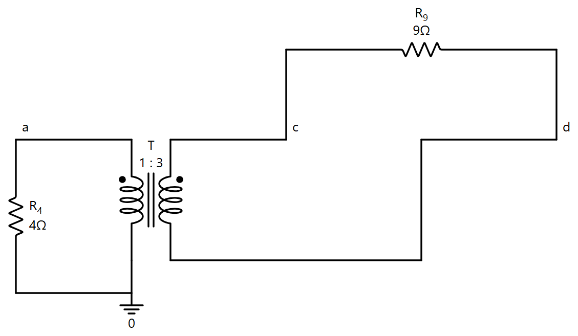
AS7's Problem 19.63, drawn by Symbulator with b as the reference the tool takes
Solution
The ports are the two windings' own terminal pairs, so the transformer is written in its four-terminal form and neither port is grounded.
r4,a,b,4
t,[a,b],[c,d],[1,3]
r9,c,d,9
z — impedance, with [a,b] and [c,d] in the node boxes. DC. Results gives z11 = 0.8 Ω, z12 = z21 = 2.4 Ω and z22 = 7.2 Ω: 4 Ω in parallel with the 9 Ω referred to the primary, 9/3² = 1 Ω; 9 Ω in parallel with the 4 Ω referred to the secondary, 36 Ω; and the transfer terms three times and a third of those.
Each side is an island — a transformer conducts nothing across — so the tool takes b and d as the two references, one per side.
AS7's Problem 19.71
Open in app ↗Open in split view
Determine the z parameters of the network of Figure 19.118: 8 Ω and 6 Ω along the top with 10 Ω hanging from their junction, 4 Ω from the upper-left terminal to the foot of that 10 Ω, a 5 Ω and a 2 Ω below, and a 1:2 transformer whose secondary is the right-hand port.

AS7's Problem 19.71 as read from the book's drawing, drawn by Symbulator with q as the reference the tool takes
Solution
As read from the figure: the upper-left terminal t1 feeds the 8 Ω and, through the 4 Ω, the node p where the 10 Ω, the 5 Ω and the primary's top meet; the lower-left terminal is q, the foot of the 5 Ω, which reaches the primary's bottom r through the 2 Ω; the secondary runs from the upper-right terminal t2, beyond the 6 Ω, to the lower-right terminal b2, both dots up.
r8,t1,j,8
r10,j,p,10
r4,t1,p,4
r5,p,q,5
r2,q,r,2
r6,j,t2,6
t,[p,r],[t2,b2],[1,2]
z — impedance, with [t1,q] and [t2,b2] in the node boxes. DC. Results gives z11 = 8.273 Ω (exactly 91/11), z12 = z21 = 10 Ω and z22 = 28 Ω.