
Lesson 10
Mutual inductance and ideal transformers
Learn how to describe a mutual inductance between two inductors or two impedances using the m element. Learn how to describe an ideal transformer using the t element.
Last updated 2023-07-08
Two coils that share a magnetic field are not two separate elements, and a circuit description has to say so. This lesson covers the two ways of saying it: m for a mutual inductance between a pair of elements, and t for an ideal transformer.
10.1How to describe mutual inductance
Textbooks give a coupled pair one of two ways, and Symbulator takes both.
- Two inductors in henries, coupled by a mutual inductance also in henries.
- Two impedances in jΩ, coupled by a mutual impedance also in jΩ. Written this way the coils are r elements with imaginary values.
Either way the coupling itself is an m element with four fields: a name starting with m, the names of the two coupled elements, and the value of the coupling. For example: m1,l1,l2,1.5
That is a mutual inductance of 1.5 H between inductors l1 and l2. In jΩ it looks the same, naming two r elements instead: m1,r1,r2,2j
A book that gives the coupling as a coefficient k rather than as an inductance is written as it states it, m1,l1,l2,k=0.5, and Symbulator works out M = k√(L₁L₂) itself. The same spelling works for coils in jΩ. NR9's Assessment Problem 9.14, the last of the problems below, is written that way.
The dots are the node order
Every coupled-inductor problem in a textbook has a dot on each coil, marking the ends that share polarity. Symbulator has no way to draw a dot, so the first node you name in each coupled element is its dotted end.
That is the whole convention, and it is the thing most likely to give you a correct-looking wrong answer. If you list the nodes of one coil the other way round, the sign of the coupling flips and every current comes back wrong.
The value of a mutual inductance can use SI prefixes.
What answers do you get? None. An m element is a statement about two other elements, not a component with its own voltage and current — its effect shows up in the currents of the elements it couples.
10.2Instructive m problems
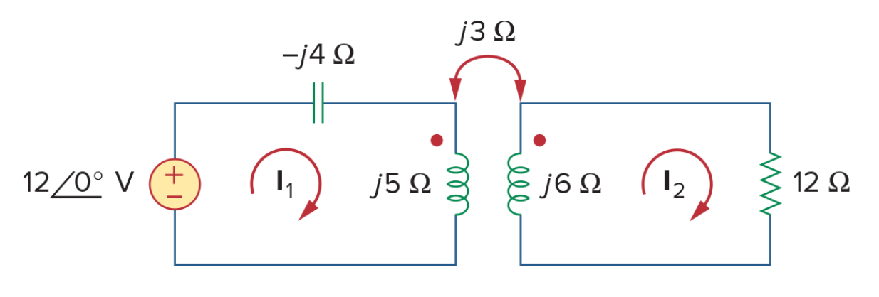
AS7's Example 13.1
Open in app ↗Open in split view
Calculate the phasor currents I1 and I2 in the circuit.
AS7's Example 13.1
Solution
Three things to notice in the description. The bottom node of both halves is ground. The coils are given in jΩ, so they are r elements with imaginary values, and the mutual is imaginary too, to match. And the dotted node of each coupled element is named first.
e,1,0,12
r1,1,2,-4j
r2,2,0,5j
m,r2,r3,3j
r3,3,0,6j
r4,3,0,12
AC, and leave RMS phasors unticked. Then read the two currents with Mini-Tools set to aa:
aa(ir2) reads 13.02∠-49.4° A and aa(ir4) reads 2.910∠14.04° A.
Both are correct.
AS7's Practice Problem 13.1
Open in app ↗Open in split view
Determine the voltage Vo in the circuit.

AS7's Practice Problem 13.1
Solution
Again the dotted node of the coupled inductor comes first.
e,1,0,(200∠45°)
r1,1,2,4
r2,2,0,8j
m,r2,r3,1j
r3,0,o,5j
r4,o,0,10
aa(vo) reads 20.00∠-134.43° V.
Correct.
AS7's Example 13.2
Open in app ↗Open in split view
Calculate the mesh currents in the circuit.

AS7's Example 13.2
Solution
Notice the node order again, matching the dots.
e,1,0,100
r1,1,2,4-3j
r2,2,0,6j
m,r2,r3,2j
r3,3,2,8j
r4,3,0,5
aa(ir1) reads 20.30∠3.5° A and aa(ir4) reads 8.693∠19.03° A.
Correct.
NR9's Assessment Problem 9.14
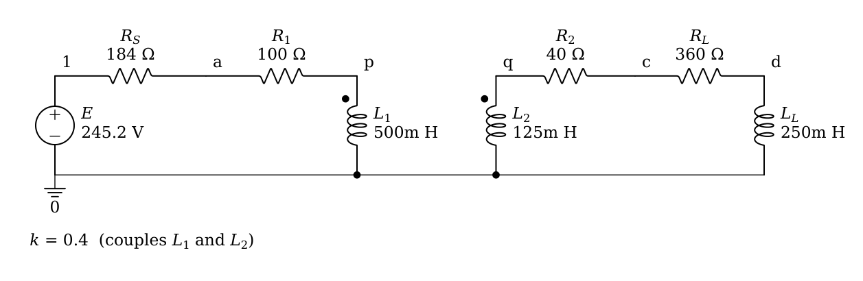
A linear transformer couples a load of a 360 Ω resistor in series with a 0.25 H inductor to a sinusoidal source of 245.20 V maximum at 800 rad/s, whose internal impedance is 184 Ω. The transformer has R1 = 100 Ω, L1 = 0.5 H, R2 = 40 Ω, L2 = 0.125 H and a coefficient of coupling k = 0.4, with the dots at the top of both coils. Calculate (a) the reflected impedance, (b) the primary current and (c) the secondary current.
NR9's Assessment Problem 9.14, drawn by Symbulator
Solution
The book gives the coupling as a coefficient, so the m line takes it as it is, m,l1,l2,k=0.4, and there is no mutual inductance to work out first. Both dots are at the top, so both coils are written top node first. We call the source's internal impedance rs, and the load's resistor and inductor rl and ll. The book draws the two sides on separate bottom rails. We join them at ground, which changes no current, because nothing conducts from one winding to the other.
e,1,0,245.2
rs,1,a,184
r1,a,p,100
l1,p,0,0.5
m,l1,l2,k=0.4
l2,q,0,0.125
r2,q,c,40
rl,c,d,360
ll,d,0,0.25
Open in app ↗Open in split view
Set Analysis to AC — alternating current and put 800 in the ω — angular frequency box. In Settings, set Rounding to approx to n digits with n = 4 and tick Show AC answers as polar phasors.
Parts (b) and (c) are read straight off the cards. The primary current is the current through r1, and the secondary current the current through r2, each in the direction of the book's arrow:
So (b) the primary current is 0.5 cos(800t − 53.13°) A, and (c) the secondary current is 0.08 cos 800t A.
(a) The reflected impedance is what the secondary adds to the impedance the source sees. The source's card reports that impedance as ze. Without the coupling it would be the source's own 184 Ω, the primary winding's 100 Ω and the primary coil's jωL₁ = j800 × 0.5 = j400 Ω, so we type the difference into Evaluate:
ze - (184 + 100 + 400j)It gives 10.24 - 7.68j Ω. All three agree with the answers the book prints. The coupling written as the inductance it stands for, m,l1,l2,0.1, gives the same, since M = 0.4 × √(0.5 × 0.125) = 0.1 H.
10.3How to describe ideal transformers
An ideal transformer has four terminals — two a side. Symbulator simulates the case where one terminal on each side is grounded, which covers the textbook problems; you name only the two live nodes.
A t element takes five fields: a name starting with t, the live node on the first side, the live node on the second side, and the turns on each side. For example: t1,1,2,80,800
That is 80 turns on the side connected to node 1 and 800 on the side connected to node 2, wound the same way. Only the ratio matters, so 1,10 would describe the same transformer.
Polarity is a minus sign. If the dots are on opposite ends, make one of the two turn counts negative: t,a,b,1,-5
It does not matter which of the two you make negative, as long as one of them is.
The turns may be written as a pair in brackets, t1,1,2,[80,800], which means exactly the same as the five-field form.
All four terminals. When neither bottom terminal is ground, write each side as a bracketed pair, top node then bottom node, and the turns as a pair:
t1,[1,3],[2,4],[80,800]That is a primary between nodes 1 and 3, a secondary between nodes 2 and 4, 80 and 800 turns. The dots sit at the two top nodes, as before. An ideal transformer conducts nothing from one side to the other, so a side with no path of its own to ground is an island: Symbulator takes one of its nodes — the winding's lower terminal — as that side's own reference, holds it at 0, and says so in a note above the results. Every current and every voltage difference on that side is the same whichever node is chosen; only its absolute potentials depend on it, and they have no meaning anyway. Either terminal of a pair may be 0, so t1,[1,0],[2,0],[80,800] is the two-node form written out.
What answers do you get? The voltages at the live nodes, as for any node in the circuit, and the current entering the transformer at each of its live nodes, named with the transformer and the node — for a transformer t on nodes 1 and 2, that is it1 and it2. With all four terminals named, there are four such currents, one per node.
10.4Instructive t problems
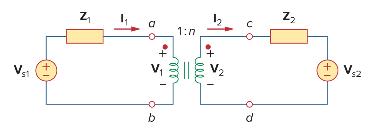
AS7's Figure 13.33
Open in app ↗Open in split view
Obtain VTh and ZEq for the part of the circuit to the right of nodes a and b.
AS7's Figure 13.33
Solution
Everything left of a and b is ignored. Note that this one is entirely symbolic — the turns ratio, the impedance and the source are all names.
t,2,3,1,n
r2,3,4,z2
e2,4,0,vs2
Find equivalent, Thévenin / Norton, nodes 2 and 0, in DC.
Results gives
Correct — the transformer refers the source by the turns ratio and the impedance by its square, which is exactly what an ideal transformer does.
AS7's Example 13.8
Open in app ↗Open in split view
For the ideal transformer circuit, find the source current I1, the output voltage Vo, and the complex power supplied by the source.

AS7's Example 13.8
Solution
One of the turn counts is negative here, because the dots are of opposite polarity.
e,1,0,120
r1,1,2,4-6j
t,2,3,1,-2
ro,3,0,20
AC, with RMS phasors ticked this time — the question asks for complex power, and that is the convention it wants.
Three readings from Mini-Tools with aa: ir1 is 11.09∠33.69° A, vro is 110.9∠-146.31° V, and -se — the complex power supplied, so the opposite of the power consumed by the source — is 1331∠-33.69° VA.
Three conversions in a row is the point at which the setting is less work than the tool: tick Show AC answers as polar phasors in Settings and the first two are already in that form when the circuit solves. The third still wants aa, because -se is an expression rather than an answer.
All three are correct.
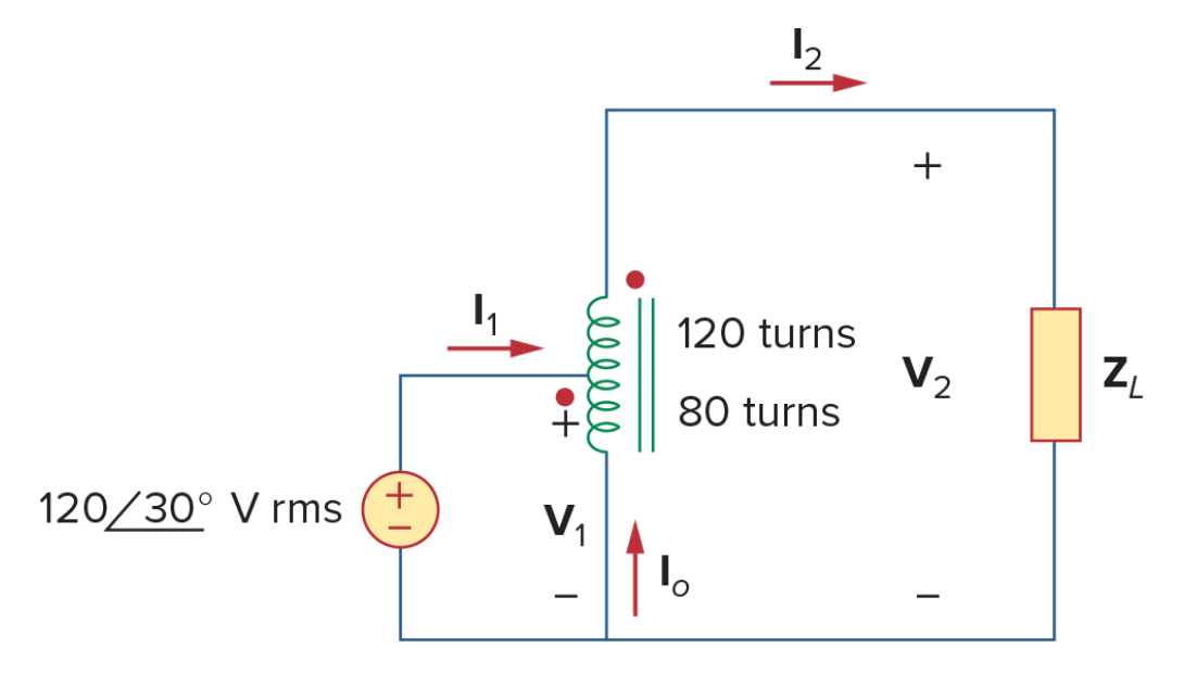
AS7's Example 13.11
Open in app ↗Open in split view
Refer to the autotransformer circuit. Calculate I1, I2 and Io if ZL = 8 + j6 Ω, and the complex power supplied to the load.
AS7's Example 13.11
Solution
Symbulator has no dedicated element for an autotransformer. The same t element does it: the input is node 1, the output is node 2, and the turns are the 80 of the lower winding and the 80 + 120 of the whole.
e,1,0,(120∠30°)
t,1,2,80,80+120
rl,2,0,8+6j
AC, with RMS phasors ticked.
This is how the three currents come out of the two the transformer reports:
- I1 is the current entering the transformer at node 1,
it1. - I2 is the opposite of the current entering it at node 2,
it2. - Io is the opposite of the sum of the two, since what enters the transformer at its two live nodes leaves it through the common one.
Results gives, under t,
so I1 is 75∠-6.87° A, I2 is the opposite of it2, 30∠-6.87° A, and Io, read with aa on -it1-it2, is 45∠173.13° A.
All three are correct.
The autotransformer as one tapped winding
Open in app ↗Open in split view
The same autotransformer, described as what it physically is: one winding with a tap. The lower section, 80 turns, runs from the tap to ground; the upper section, 120 turns, runs from the top of the winding down to the tap. Find I1 and I2 again.
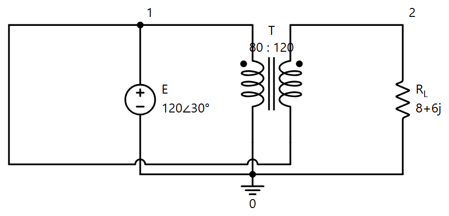
The autotransformer as one tapped winding, drawn by Symbulator
Solution
The second winding's bottom terminal is the first winding's top, node 1, so this needs the four-terminal form: the first winding is the pair [1,0], the second the pair [2,1].
e,1,0,(120∠30°)
t,[1,0],[2,1],[80,120]
rl,2,0,8+6j
AC, with RMS phasors ticked. Results gives, under t,
Node 1 is a terminal of both windings, so it1 is the total entering the transformer there, which is the source current I1, 75∠-6.87° A; and I2 is the opposite of it2, 30∠-6.87° A. The same answers as with the two-node description above, from a description that looks like the circuit.
A transformer whose primary is not grounded
Open in app ↗Open in split view
A 10 V source feeds a 1 Ω resistor and then the primary of a 2:1 ideal transformer; the far end of the primary returns to ground through a 3 Ω resistor. The secondary is grounded and drives an 8 Ω load. Find the load current and the current into each terminal of the transformer.
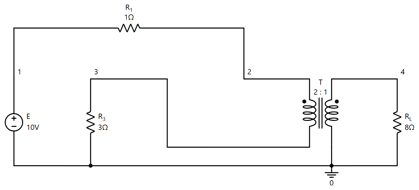
A transformer whose primary is not grounded, drawn by Symbulator
Solution
The primary sits between nodes 2 and 3, neither of them ground, so it is written as the pair [2,3]; the secondary's bottom is ground, and the pair [4,0] says so.
e,1,0,10
r1,1,2,1
t,[2,3],[4,0],[2,1]
r3,3,0,3
rl,4,0,8
DC. Results gives, under t,
and irl is 5/9 A. Check: the 8 Ω load reflects to the primary as 8 × (2/1)² = 32 Ω, in series with 1 + 3 Ω, so the primary current is 10/36 = 5/18 A, entering at node 2 and leaving at node 3; the 2:1 ratio doubles it on the secondary, where it4 is negative because that current is leaving the transformer into the load.
Both windings between live nodes, and why a side needs a ground
Open in app ↗Open in split view
The same 2:1 transformer, now with its secondary between two live nodes as well: the 100 Ω load sits across the secondary, and node 5 is tied to ground through a 7 Ω resistor. Find the currents.
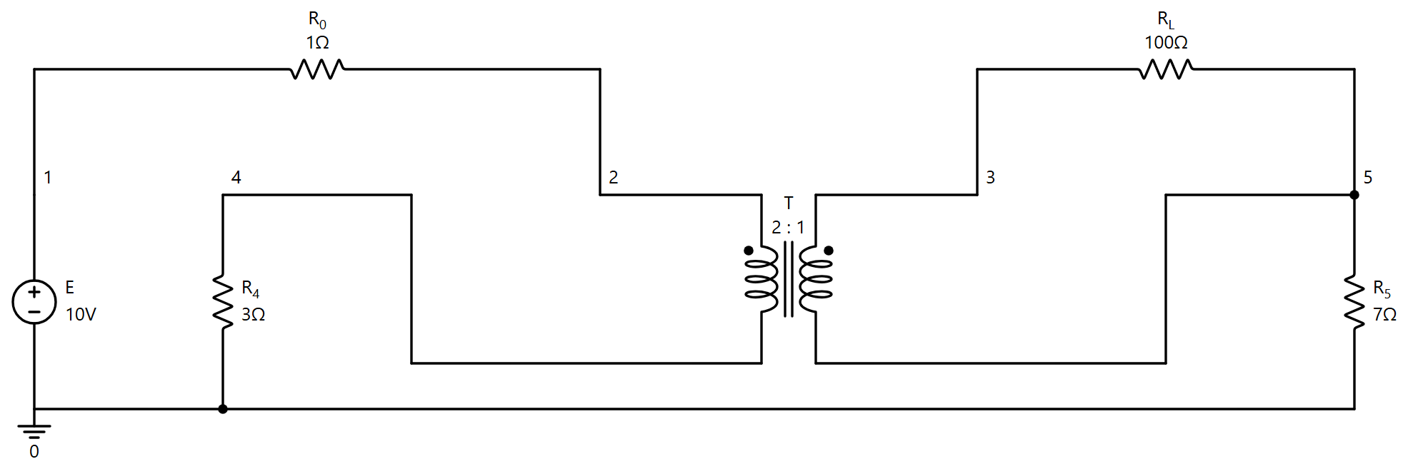
Both windings between live nodes, drawn by Symbulator
Solution
e,1,0,10
r0,1,2,1
t,[2,4],[3,5],[2,1]
r4,4,0,3
rl,3,5,100
r5,5,0,7
DC. Results gives, under t,
and ir5 is 0: the secondary's current circulates through the load alone, and the resistor to ground carries nothing. What it does is give the secondary side a reference. An ideal transformer conducts nothing from one winding to the other, so without r5 that side would have no path to node 0 at all — delete it and Symbulator still solves, taking node 5 as the side's own reference and saying so in a note: Node(s) 5, 3 have no path to node 0 (they lie behind a port or a coupling), so their voltages are measured against 5, taken as 0. The currents and v3 − v5 come out the same either way; only the two absolute potentials differ, and on a real bench they would be whatever the wiring made them.
10.5Switching with coupled coils
Seven problems from Nilsson and Riedel's Electric Circuits: four from the 11th edition, each with a switch that moves at t = 0 and a pair of coupled coils on the far side of it, and three from the 12th, in which a switch closes onto a source with nothing stored. The method is the one Lesson 6 uses for every switch: a DC solve before the switch gives the coil currents, and those become the initial conditions of a transient solve after it — or simply zeros, when the book says no energy is stored. In the first four the coupled side has no ground of its own, and none is needed: a coupling conducts nothing across, so Symbulator takes one node of that side as its reference and says so. The variable asked for is the one the book marks in blue.
NR11's 60 V source and coupled 2 H and 8 H coils
A 60 V source feeds a 9 Ω resistor and, through a switch at a, a 3 Ω resistor in series with a 2 H coil. The coil is coupled, M = 2 H, to an 8 H coil closed on 2 Ω and 10 Ω. The switch has been at a a long time and moves to b at t = 0, shorting the 3 Ω and the 2 H together. Find i1 in the 2 H coil and i2 in the 8 H coil for t > 0. Both dots are at the coils' upper ends.
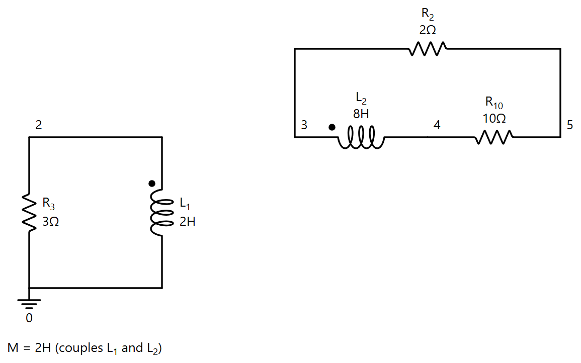
The circuit after the switch, drawn by Symbulator
Solution
Before the switch, in DC, with the source in and the switch at a:
e,1,0,60
r9,1,a,9
r3,a,2,3
l1,2,0,2
l2,3,4,8
r2,3,5,2
r10,5,4,10
m,l1,l2,2
DC, t < 0Open in app ↗Open in split view
Both coils are shorts in DC, so il1 = 5 A (60 V over 9 + 3 Ω) and il2 = 0. The secondary has no path to node 0, and the results say so in a note: its voltages are measured against node 4.
After the switch the source is gone and the 3 Ω and the 2 H are shorted through b; the 5 A is the coil's initial condition. In TR:
r3,0,2,3
l1,2,0,2,5
l2,3,4,8,0
r2,3,5,2
r10,5,4,10
m,l1,l2,2
TR, t > 0Open in app ↗Open in split view
Two modes, at 1 and 3 per second: i1 starts from 5 A and i2 from 0, and both vanish. Both satisfy the pair of coil equations exactly, which is how they were checked.
NR11's two switches and coupled 3 H and 15 H coils
On the left, a 24 V source and 120 Ω feed a 3 H coil through switch 1, which has been open a long time and closes at t = 0. On the right, a 15 H coil, coupled to the first by M = 3 H, is connected through switch 2 to either a — a 10 Ω resistor and a 20 V source — or b, a 360 Ω resistor. Switch 2 has been at a a long time and moves to b at t = 0. Find i1 for t > 0. The dot of the 3 H coil is at its upper end, the dot of the 15 H coil at its lower end.
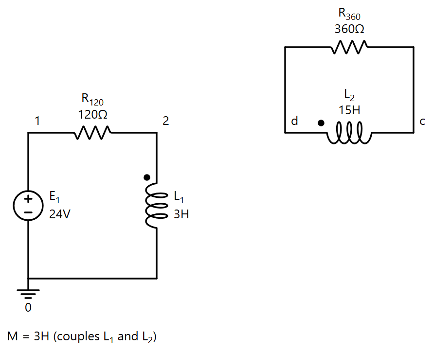
The circuit after the switches, drawn by Symbulator
Solution
Before the switches there is no primary current at all, and the 20 V drives 2 A through the 10 Ω and down through the 15 H coil. In DC:
e,a,0,20
r10,a,c,10
l2,d,c,15
DC, t < 0Open in app ↗Open in split view
The dot of the 15 H coil is at its bottom, so its first node is d, the bottom, and the current from d to c reads il2 = -2 A.
After the switches the 24 V drives the primary from rest and the secondary, starting at 2 A, decays through the 360 Ω. In TR, ticking Do you want to limit the results to save time? and asking for the one current:
il1e1,1,0,24
r120,1,2,120
l1,2,0,3,0
l2,d,c,15,-2
r360,c,d,360
m,l1,l2,3TR, t > 0Open in app ↗Open in split view
It starts from 0, settles at 24/120 = 0.2 A, and its two modes are at 20 and 60 per second. The dots are at opposite ends, which is why the secondary is written bottom node first with a positive M; writing it top node first with M = −3 gives the same answer.
NR11's 90 V source and coupled 3 H and 2 H coils
A 90 V source and 5 Ω feed, through a switch at a, a 3 H coil whose far end joins a 2 H coil and a 10 Ω resistor to ground; the coils are coupled, M = 1 H, dots at both upper ends. The switch has been at a a long time and moves to b at t = 0, replacing the source by a 20 Ω resistor. Find io, the current into the 3 H coil, for t > 0.
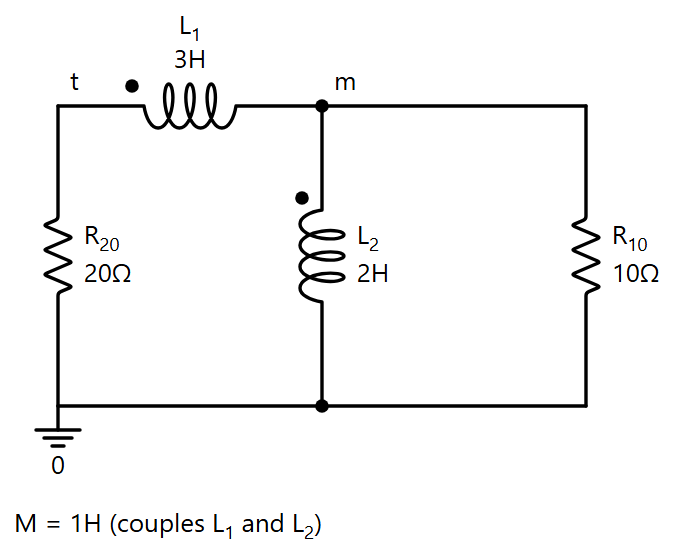
The circuit after the switch, drawn by Symbulator
Solution
Before the switch both coils are shorts in DC, and the 2 H shorts the 10 Ω:
e,1,0,90
r5,1,t,5
l1,t,m,3
l2,m,0,2
r10,m,0,10
m,l1,l2,1
DC, t < 0Open in app ↗Open in split view
il1 = 18 A, il2 = 18 A and ir10 = 0: all of it goes through the coils.
After the switch, in TR, asking only for il1 in the same way:
r20,t,0,20
l1,t,m,3,18
l2,m,0,2,18
r10,m,0,10
m,l1,l2,1
TR, t > 0Open in app ↗Open in split view
From 18 A to zero, with modes at 2 and 20 per second.
NR11's capacitor shorted by a switch, coupled 0.8 H and 1.6 H coils
A 48 V source feeds a 10 mF capacitor, a 4 Ω resistor and a 0.8 H coil in series. A switch across the capacitor has been closed a long time and opens at t = 0. The coil is coupled, M = 0.8 H, to a 1.6 H coil across a 20 Ω resistor; both dots are at the upper ends. Find vo, the voltage across the 20 Ω, for t > 0.
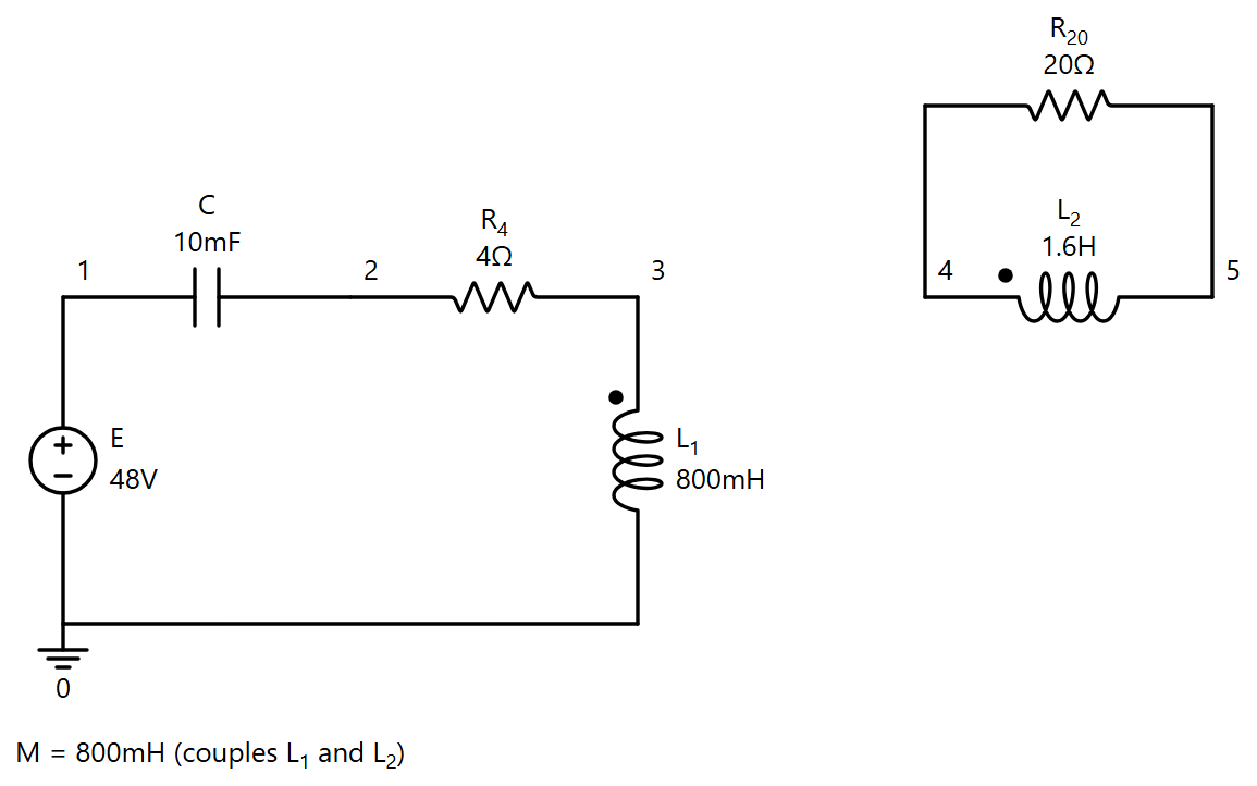
The circuit after the switch opens, drawn by Symbulator
Solution
Before the switch the capacitor is shorted, so it is left out of the DC picture:
e,1,0,48
r4,1,3,4
l1,3,0,0.8
l2,4,5,1.6
r20,4,5,20
m,l1,l2,0.8
DC, t < 0Open in app ↗Open in split view
il1 = 12 A and il2 = 0.
After the switch opens the capacitor enters the loop, uncharged, with the coil carrying its 12 A. In TR, and then in Evaluate:
v4-v5e,1,0,48
c,1,2,10'm,0
r4,2,3,4
l1,3,0,0.8,12
l2,4,5,1.6,0
r20,4,5,20
m,l1,l2,0.8TR, t > 0Open in app ↗Open in split view
A damped oscillation at 10 rad/s, the primary's series RLC, plus the secondary's own mode at 25 per second; it starts from 0 and returns to 0. Since the secondary's reference is node 5, v4 alone reads the same thing.
NR12's Problem 7.68
There is no energy stored in the circuit when the switch closes at t = 0. A 200 V source and 50 Ω feed a 4 H coil in series with an 8 H coil, coupled by M = 5 H; the 4 H coil's dot is at its left end, the 8 H coil's at its bottom. Find i(t), v1(t) across the 4 H and v2(t) across the 8 H, and say whether the answers make sense.
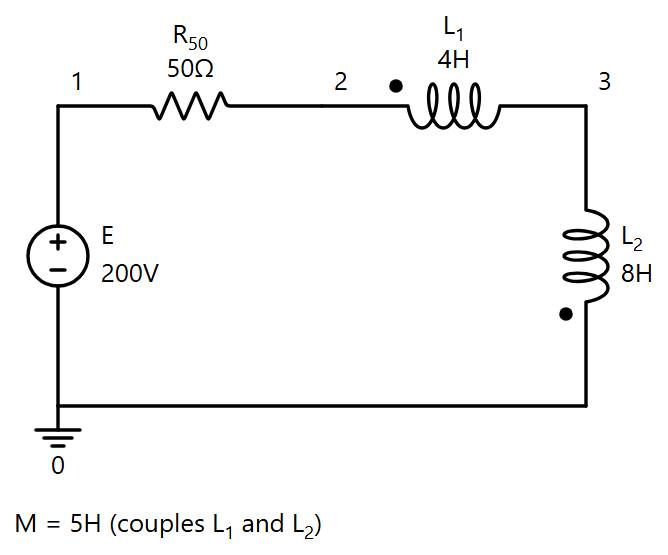
NR12's Problem 7.68, drawn by Symbulator
Solution
The current enters the 4 H at its dot and the 8 H at its undotted end, so the 8 H is written bottom node first and the pair opposes:
e,1,0,200
r50,1,2,50
l1,2,3,4,0
l2,0,3,8,0
m,l1,l2,5
Open in app ↗Open in split view
In TR, with the fifth field of each coil, the initial current, at 0:
and Evaluate with v2-v3 gives v1 = \(-100\,e^{-25t}\) V. The pair reduces to 4 + 8 − 2·5 = 2 H, whence the 25 per second (2 H over 50 Ω), and v1 is negative because the 5 H coupling outweighs the coil's own 4 H; the two voltages still add to \(200\,e^{-25t}\), which is 200 − 50 i.
NR12's Problem 7.70
There is no energy stored when the switch closes. A 10 V source and 250 Ω feed a 0.5 H coil and a 0.25 H coil in parallel, coupled by M = 0.25 H; the 0.5 H coil's dot is at its top, the 0.25 H coil's at its bottom. Find io, vo, i1 and i2, both branch currents taken downward.
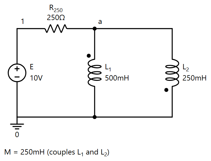
NR12's Problem 7.70, drawn by Symbulator
Solution
The 0.25 H coil is written bottom node first, since that is its dotted end:
e,1,0,10
r250,1,a,250
l1,a,0,0.5,0
l2,0,a,0.25,0
m,l1,l2,0.25
Open in app ↗Open in split view
TR. Results gives ir250 = io = \(0.04(1 -\,e^{-5000t})\) A, va = vo = \(10\,e^{-5000t}\) V and il1 = i1 = \(0.016(1 -\,e^{-5000t})\) A; i2 is downward, the opposite of il2, so Evaluate with -il2 reads \(0.024(1 -\,e^{-5000t})\) A. The parallel pair opposes and reduces to (0.5·0.25 − 0.25²)/(0.5 + 0.25 + 2·0.25) = 0.05 H, whence the 5000 per second with 250 Ω.
NR12's Problem 7.71
There is no energy stored when the switch closes. A 15 V source and 75 Ω feed an 8 mH coil and a 20 mH coil in parallel, coupled by M = 10 mH, both dots at the top. Find io, vo, i1 and i2.
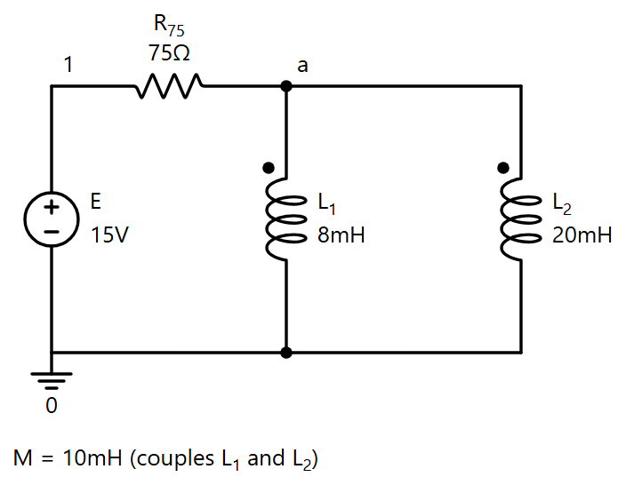
NR12's Problem 7.71, drawn by Symbulator
Solution
Both coils are written top node first:
e,1,0,15
r75,1,a,75
l1,a,0,8'm,0
l2,a,0,20'm,0
m,l1,l2,10'm
Open in app ↗Open in split view
TR. Results gives ir75 = io = \(0.2(1 -\,e^{-10000t})\) A, va = vo = \(15\,e^{-10000t}\) V, il1 = i1 = \(0.25(1 -\,e^{-10000t})\) A and il2 = i2 = \(-0.05(1 -\,e^{-10000t})\) A. The pair aids and reduces to (160 − 100)/(28 − 20) mH = 7.5 mH, whence the 10 000 per second with 75 Ω. The backwards i2 is the part worth a second look: with both coils shorts at the end, the split between the branches is set by their flux linkages rather than by resistance, and 0.25 − 0.05 is the 0.2 A the 75 Ω allows.