
Lesson 3
Current sources, conductances and dependent sources
Learn how to describe a current source using the j element. Simplify parallel resistors using the pr function and its shorthand. Learn to describe conductances and dependent sources.
Last updated 2023-07-08
In this lesson you will learn how to describe a current source with the j element, and a trick to simplify parallel resistors with the pr function or its shorthand. You will also learn to describe conductance and dependent sources using elements you already know.
3.1How to describe a current source
You can use SI prefixes here as well. The value of a current source is often given in milliamps; Symbulator will interpret any 'm given in the value as a division by a thousand.
Answers for a current source
For each current source you get the same answers as for a voltage source, with the same polarity conventions: the voltage drop in it, the current through it, the power consumed by it (for the delivered power, ask for the negative), and the equivalent resistance of the rest of the circuit as seen by that source.
Let's see an example.
B11's Example 8.1
Open in app ↗Open in split view
Given the circuit, determine the current and voltage drop in R1.

B11's Example 8.1
Solution
The circuit:
j,0,1,10'm
r1,1,0,20'k
Two lines, two elements. Leave Type of analysis on Solve circuit, set Analysis to DC — direct current, and click Run Symbulator. The circuit is numerical, so set Rounding to approx to n digits with n = 3 and tick Use SI prefixes, as in Lesson 1.
We read:
3.2What about conductances?
Conductances are really resistors by another name. So we describe them as resistors, using the element r, and give as the value the inverse of the conductance: one divided by the conductance is the resistor in Ω.
The next example is from Elementary Linear Circuit Analysis (2ed) by Leonard S. Bobrow, which from here on I call Bo2.
Bo2's Example 2.2
Open in app ↗Open in split view
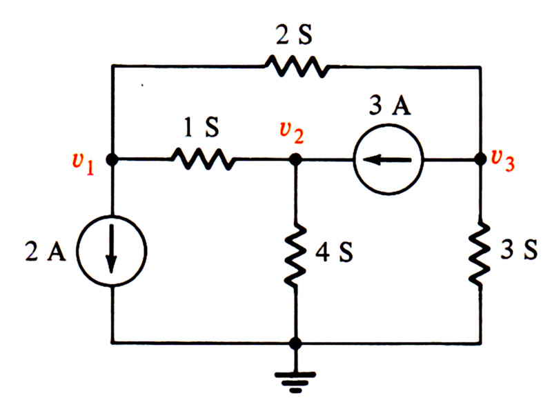
Given the circuit, determine the voltages in the nodes.
Bo2's Example 2.2
Solution
As I explained, all conductances are simulated as resistors: the 4 siemens conductance becomes a 1/4 resistor, and so on. My description:
j10,1,0,2
r12,1,2,1
r20,2,0,1/4
r30,3,0,1/3
r13,1,3,1/2
j32,3,2,3
Run it in DC. The answers are under Node voltages:
That indicates v1 = –1.3 V, v2 = .34 V, v3 = –1.12 V. This is correct.
3.3How to reduce parallel resistors
Symbulator has a function for reducing resistors (and impedances) in parallel, pr(). You can use it in the circuit description and in the Evaluate area.
To reduce three resistors in parallel with values of 10 Ω, 20 Ω and 30 Ω:
pr(10, 20, 30)You get 60/11 Ω with Rounding on exact, or 5.45 Ω approximately. It nests as deeply as you like, as the two problems below show, and it works on symbols: pr(r1, r2) gives
AS7's Example 2.10
Find the equivalent resistance.

AS7's Example 2.10
Solution
No simulation needed: the whole reduction is one nested expression in Evaluate, from the far end of the ladder outward:
10 + pr(3, 6, 1 + pr(12, 4, 1 + 5))The answer is 11.2 Ω. This is correct.
AS7's Practice Problem 2.10
Find the equivalent resistance.

AS7's Practice Problem 2.10
Solution
Again, no simulation:
16 + pr(18, 9, 2 + pr(20, 1 + pr(5, 20)))The answer is 19 Ω. This is correct.
The [r,r,r…] shorthand
There is a shorthand for pr: put the resistor values in square brackets, separated by commas. Expressions like [10,20,30] or [r1,r2,r3,r4] are read as inputs to pr, both in the Evaluate area or in the circuit description.
When to reduce resistors
A simulation where it makes sense to use pr is B11's Example 7.4, which you saw in the practice problems of Lesson 1. It makes sense to reduce R4 and R5 to an equivalent resistor, since we do not need to know their individual currents or power use.
The [6,3] below is the shorthand at work:
e,1,0,16.8
r1,1,2,9
r2,1,2,6
r3,2,3,4
re1,3,0,[6,3]
r6,2,0,3
Run it in DC. The current the source delivers is the opposite of ie: 3 A.
An example where using pr makes no sense is B11's Example 6.13, because you need to know the current through each resistor.
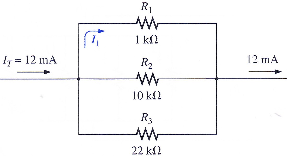
Finally, a simulation where you can reduce part of the resistors is B11's Example 6.22. We must leave R1 alone, because we need the current through it, but we can reduce R2 and R3:
jt,0,1,12'm
r1,1,0,1'k
re,1,0,[10'k,22'k]
Moving forward, we will use pr(,,), or its shorthand [,,], in circuit descriptions whenever we feel it is appropriate.
3.4How to describe dependent sources
One of my favourite scenes in cinema comes from The Dark Knight: the Joker, played masterfully by Heath Ledger, is rolling on the floor of a Gotham City prison, taking a bare-knuckle beating from an ever-more-frustrated Batman. Master of the situation and laughing hysterically, the Joker says: "You have nothing! Nothing to threaten me with!"
Even though the movie had not been made yet, I remember feeling something similar — if less hysterical — back in 1999, when I realised that a 100% symbolic implementation let me make any element's value depend on any answer of the circuit. I could simulate voltage or current sources dependent on any voltage, current or combination of them as easily as a 12 V source.
Here is what you need to know for simulating dependent sources in Symbulator: nothing. There is nothing special to it at all. Just write the value as a function of the circuit's answers, using the answer names you know by now, and run the simulation like it's nobody's business. For example:
- if the source depends on the current through a resistor called r1, you define its value as
ir1 - if the source depends on the voltage drop in a resistor called r2, you define its value as
vr2 - if the source depends on the current through a short called s3, you define its value as
is3 - if the source depends on the difference between the voltage of two nodes a and b, you define its value as
va-vb
With Symbulator, instead of fearing them, you will laugh in the face of dependent sources, thinking: "You have nothing!" Booyah!
3.5Instructive solved examples
Circuits with E, J and R
B11's Example 8.2
Open in app ↗Open in split view
Determine the values of VS, I1 and I2.
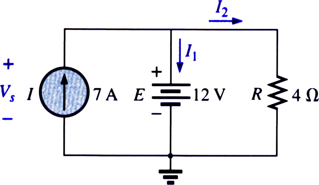
j,0,1,7
e,1,0,12
r1,1,0,4
The answers you want are v1, ie and ir1, in Results.
The answers show VS is 12V, I1 is 4A and I2 is 3A. All correct.
B11's Example 8.15
Open in app ↗Open in split view
Determine the current through each resistor. My solution, with the direction marked in blue:
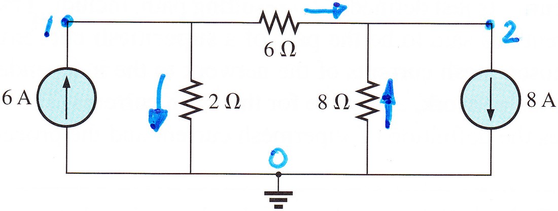
j6,0,1,6
r2,1,0,2
r6,1,2,6
r8,0,2,8
j8,2,0,8
The answers you want are ir2, ir6 and ir8, in Results.
Here we use Rounding — approx to n digits, with n = 3.
The answer is IR2 = 1.25A, IR6 = 4.75A and IR8 = 3.25A.
B11's Example 8.21
Open in app ↗Open in split view
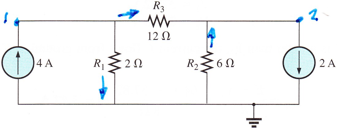
Determine the voltage in each node and the current through each resistor.
My solution:
j1,0,1,4
r1,1,0,2
r3,1,2,12
r2,0,2,6
j2,2,0,2
The answers you want are v1, v2, ir1, ir2 and ir3, in Results.
The answer is V1=6V, V2=-6V, IR1=3A and IR2=IR3=1A.
Bo2's Drill Exercise 2.2 (Conductances)
Open in app ↗Open in split view
Given the circuit, determine the voltages in the nodes.

Below my solution:
r10,1,0,1/3
r12,1,2,1/2
r13,1,3,1/2
r23,2,3,1/6
r20,2,0,1/8
j12,1,2,17
j03,0,3,2
The answers you want are v1, v2 and v3, in Results.
Here we use Rounding — approx to n digits, with n = 3.
The answer is v1=-2V, v2=1V and v3=0.5V. This is correct.
HK5's Figure 1-24b (Expert)
Open in app ↗Open in split view
Determine ix and vx in the following circuit.

My solution:
j6,0,1,6
r5,1,2,5
r2,2,0,2
r1,1,3,1
r3,0,4,3
j10,2,3,10
rx,3,4,rx
Set Analysis to DC — direct current. This one needs Enable Expert Mode ticked in the Expert Mode box; the equations and unknowns go in the fields it reveals.
The answers you want are ir1 and vrx, in Results.
In DC, with ir2=4 in Add equation(s) and rx in Add unknown(s), run it. The answer is ix = -8A and vx = 80V.
HK5's Example 2.2 (Conductances)
Open in app ↗Open in split view
Determine the voltages in the nodes. My solution:

j01,0,1,-8
j30,3,0,-25
j21,2,1,-3
r12,1,2,1/3
r23,2,3,1/2
r13,1,3,1/4
r20,2,0,1
r30,3,0,1/5
The answers you want are v1, v2 and v3, in Results.
The answer is v1=1V, v2=2V and v3=3V. This is correct.
B11's Example 8.5
Open in app ↗Open in split view
Determine the current I2 in the circuit shown. My solution:

j1,1,0,4
r1,1,0,3
e2,1,2,5
r2,0,2,2
This gives us a value for I2 of 3.4 A. This is correct.
Bo2's Example 2.5 (Conductances)
Open in app ↗Open in split view

Determine the voltages in the nodes, and the current through the voltage source.
j,0,1,3
e,3,2,3
r12,1,2,1/7
r20,2,0,1/3
r30,3,0,1/5
r13,1,3,1/2
The answers you want are v1, v2 and v3, in Results; i is the opposite of ie.
Here we use Rounding — approx to n digits, with n = 3.
The answer is v1=-.5, v2=-1.5, v3=1.5 and i=11.5. This is correct.
B11's Example 8.22
Open in app ↗Open in split view
Determine V1 and V2. My solution:
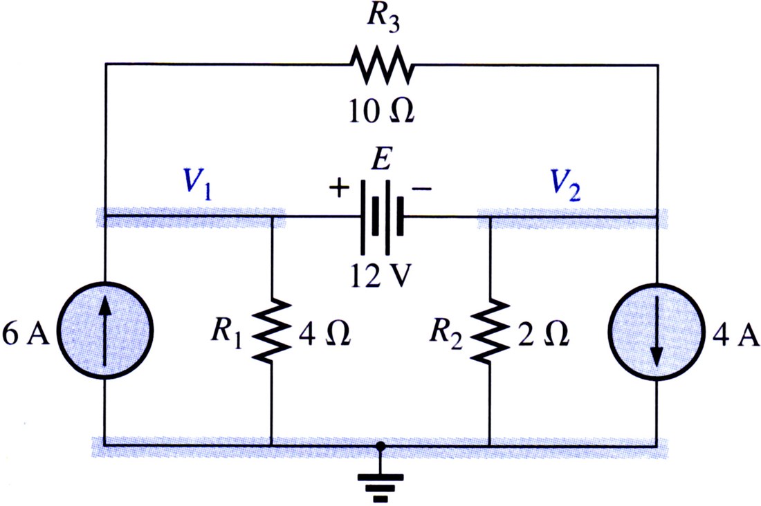
j1,0,1,6
r1,1,0,4
e,1,2,12
r3,1,2,10
r2,2,0,2
j2,2,0,4
The answers you want are v1 and v2, in Results.
Here we use Rounding — approx to n digits, with n = 3.
The answer is V1 = 10.67V and V2 = -1.33V.
B11's Example 8.19
Open in app ↗Open in split view
Determine V1, I1 and I2, in the circuit:
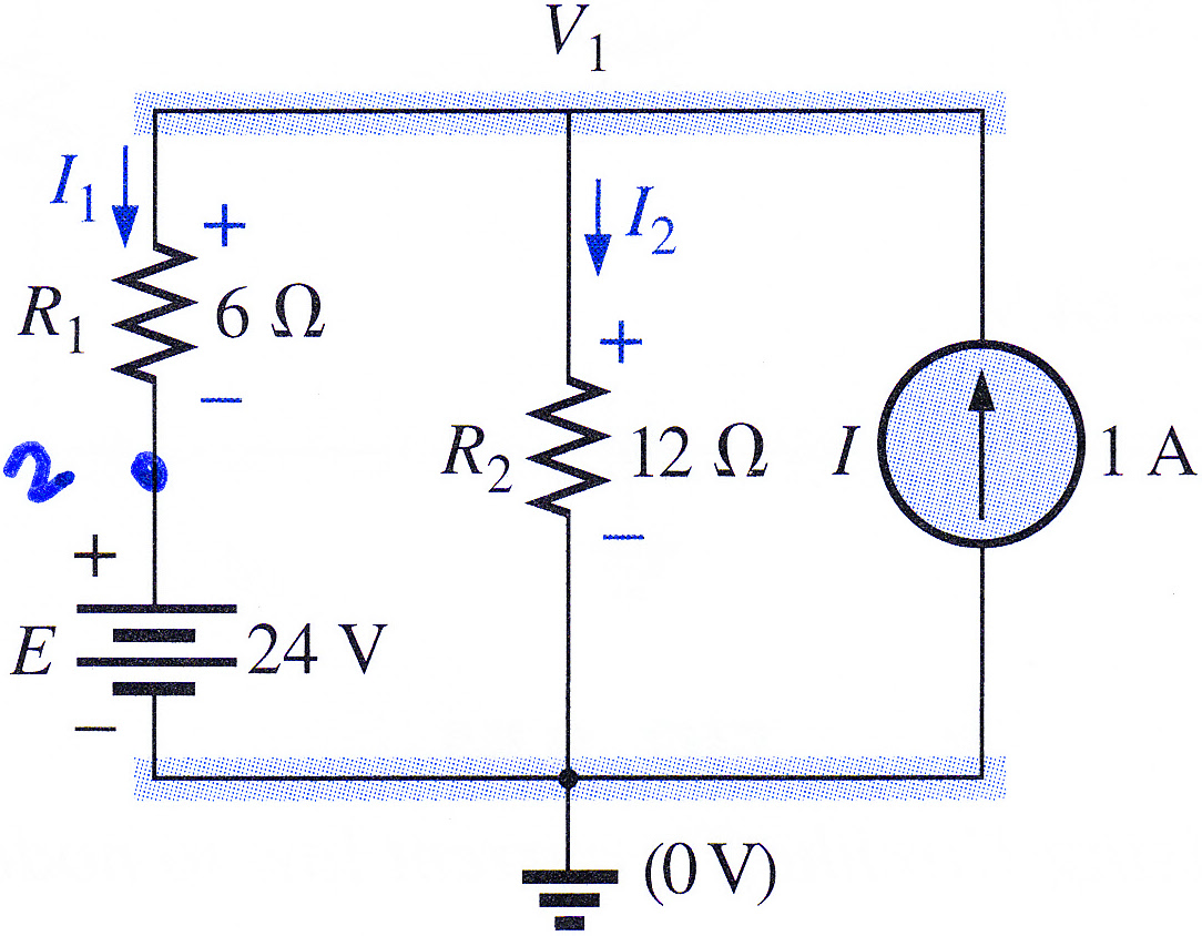
My solution:
e,2,0,24
r1,1,2,6
r2,1,0,12
j,0,1,1
The answer is V1 = 20V, I1 = -.667A and I2 = 1.67 A.
B11's Example 8.14
Open in app ↗Open in split view
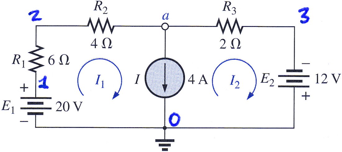
Determine I2 and I3.
e1,1,0,20
r1,1,2,6
r2,2,a,4
j,a,0,4
r3,a,3,2
e2,0,3,12
The answers you want are ir2 and ir3, in Results.
Here we use Rounding — approx to n digits, with n = 3.
The answers are:
This is correct.
B11's Example 8.20
Open in app ↗Open in split view
Determine V1, V2, I1, I2 and I3. My solution:
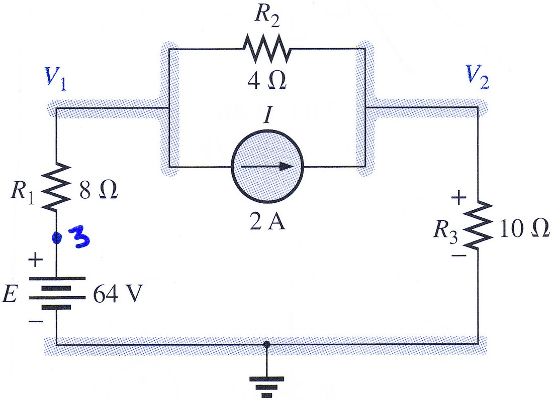
e,3,0,64
r1,3,1,8
r2,1,2,4
j,1,2,2
r3,2,0,10
The answers you want are v1, v2, ir1, ir2 and ir3, in Results.
Here we use Rounding — approx to n digits, with n = 3.
The answer is V1 = 37.82V, V2 = 32.73V, I1 = 3.27A, I2 = 1.27A and I3 = 3.27A.
RM3's Example 9-12 (solve)
Open in app ↗Open in split view
If R3 is to be replaced with R4 and I4, determine the value and direction of the source.
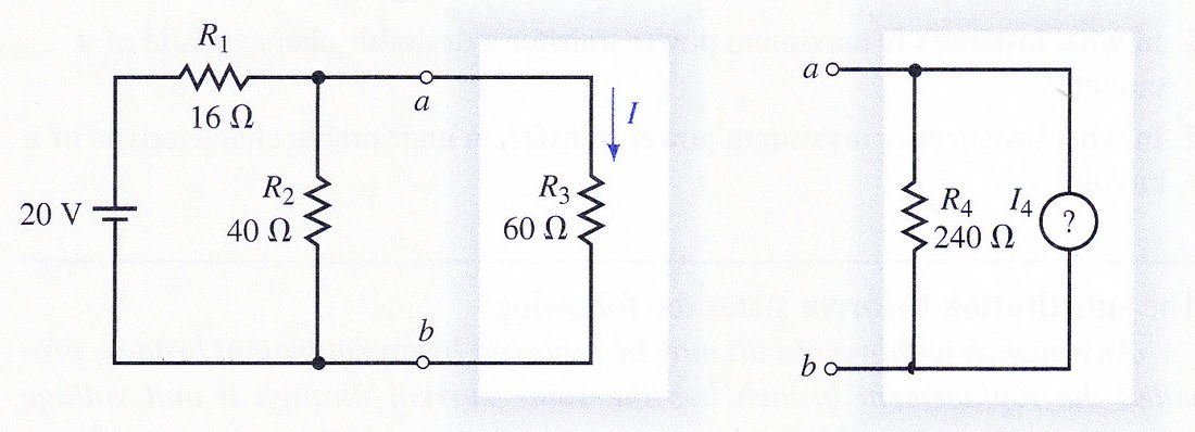
So that we can keep the name of node b, we will use the top left node as reference.
First, make sure you understand what this problem is asking you to do. The idea is that, despite the change, we keep the same voltage drop and current flow between nodes a and b. We must first know what they are. So we simulate the original circuit:
e,0,b,20
r1,0,a,16
r2,a,b,40
r3,a,b,60
The answer you want is ir3, in Results.
Ask Evaluate for:
va-vbWe find that the voltage drop is 12V and the current is 0.2A. These are the currents and voltages that we have to keep once we do the replacement. Simulate the circuit now replacing R3 with a resistor R4 of 240Ω and a source j with value I4. Run this:
e,0,b,20
r1,0,a,16
r2,a,b,40
r4,a,b,240
j,a,b,i4
Step 2Open in app ↗Open in split view
Notice that both the voltage drop (given by va-vb) and the current (given by ir4+ij) are algebraic functions in terms of i4. Now you can find i4 solving by voltage drop:
Either equation goes in the Solve card:
va-vb = 12with i4 as the unknown — or ir4+ij = 0.2 for the same answer by current instead.
The result is the same: i4 = .15 A. The required current source is .15A from a to b.
RM3's Example 8-13
Open in app ↗Open in split view
Solve for the currents through R2 and R3 in the circuit shown. My solution:

r1,a,0,10'k
r2,1,0,5'k
r3,b,a,6'k
r4,0,2,16'k
j,a,b,2'm
e1,1,b,10
e2,b,2,8
The answers you want are ir2 and ir3, in Results.
Here we use Rounding — approx to n digits, with n = 3.
The answer is IR2 = 1.54 mA and IR3 = 1.11 mA. This is correct.

HK5's Figure 1-24c (Expert)
Open in app ↗Open in split view
Determine ix and vx in the following circuit.

e,1,0,60
r8,1,2,8
r10,2,0,10
r4,2,3,4
r2,3,0,2
j,0,3,ix
Set Analysis to DC — direct current. This one needs Enable Expert Mode ticked in the Expert Mode box; the equations and unknowns go in the fields it reveals.
The answers you want are ix and v3, in Results.
In DC, with ir8=5 in Add equation(s) and ix in Add unknown(s), run it. The answer is ix = 1A and vx = 8V. This is correct.

Bo2's Example 1.9
Open in app ↗Open in split view
Determine I1, I2 and v.
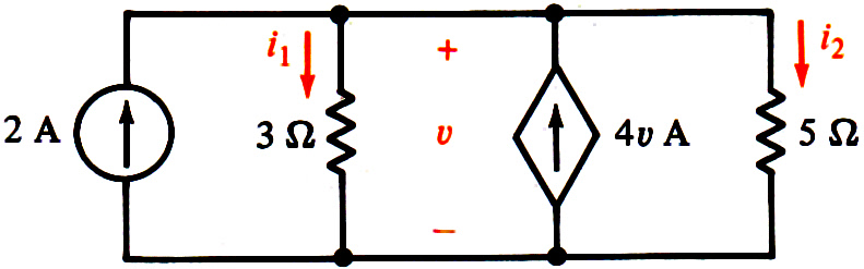
This is my solution.
ji,0,1,2
r1,1,0,3
jd,0,1,4*v1
r2,1,0,5
The answers you want are ir1, v1 and ir2, in Results.
The answer is I1=-5/26 A, I2=-3/26 A and v=-15/26 V. This is correct.
AS2's Practice Problem 2.7
Open in app ↗Open in split view
Find vo and io in the circuit. My solution:

ji,0,o,6
ro,o,0,2
jd,o,0,iro/4
r8,o,0,8
The answers you want are vo and iro, in Results.
The answer is vo = 8 V and io = 4 A. This is correct.
HK5's Example 1-3
Open in app ↗Open in split view
Determine the power delivered by each source and consumed by both resistors.

ei,1,0,120
r1,1,2,30
ed,2,3,2*vra
ra,0,3,15
The power each source delivers is the opposite of pei and of ped. For the resistors together, ask Evaluate for:
pr1+praThe independent source delivers 960W, the dependent source delivers 1920W, and the resistors consume 2880W together. This is correct.
AS2's Practice Problem 2.6
Open in app ↗Open in split view
Find vx and vo in the circuit. My solution:

ei,x,1,35
rx,x,0,10
ed,0,2,2*vx
ro,1,2,5
The answers you want are vx and vro, in Results.
The answer is vx =10 and vo =-5. This is correct.
Bo2's Example 1.10
Open in app ↗Open in split view
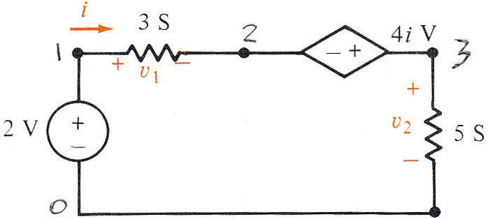
Determine v1, v2 and i. My solution:
ei,1,0,2
r1,1,2,1/3
ed,3,2,4*ir1
r2,3,0,1/5
The answers you want are ir1, vr1 and vr2, in Results.
The answer is v1=-5/26 V, v2=-3/26 V and i=-15/26 A. This is correct.
AS2's Example 2.6
Open in app ↗Open in split view
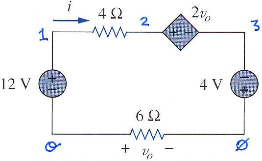
Determine vo and i in the circuit. My solution is shown below:
e12,1,o,12
ri,1,2,4
ed,2,3,2*vo
e4,0,3,4
ro,o,0,6
The answers you want are vo and iri, in Results.
The answer is vo =48 and i = -8. This is correct.
HK5's Drill Problem 1.11
Open in app ↗Open in split view
Find the power absorbed by each element in the circuit. My solution:

r1,x,0,30
ei,1,x,12
r2,1,2,8
r3,2,3,7
ed,3,0,4*vx
The answers you want are pr1, pr2 and pr3 in Results, and for the two sources the power delivered row of each card, -pei and -ped.
Here we use Rounding — approx to n digits, with n = 3.
The answers are:
This is correct: the source ei delivers a negative power, which is to say it absorbs 1.92 W, and ed delivers 3.072 W.
AS2's Example 3.6
Open in app ↗Open in split view
Determine the value of Io in the circuit. My solution:
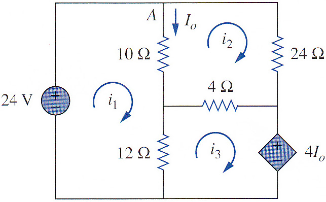
ei,a,0,24
ro,a,b,10
r12,b,0,12
r4,b,c,4
r24,a,c,24
ed,c,0,4*iro
The answer you want is iro, in Results.
Here we use Rounding — approx to n digits, with n = 3.
The answer, 1.5 A, is correct.
Bo2's Drill Exercise 1.12
Open in app ↗Open in split view
Determine i, v and id.

We are given an unnecessary piece of information: the 4V drop in the 2Ω resistor.
My solution:
ei,1,0,10
r1,1,2,1
r2,2,3,2
r3,2,0,3
r4,3,0,2
ed,2,3,ir1/2
The answers you want are ir1, vr3 and ied, in Results.
The answer is i=4, v=6 and id=1. This is correct.
AS2's Example 3.2
Open in app ↗Open in split view
Determine the voltages at the nodes.

My solution:
ji,0,1,3
jd,3,0,2*ir2
r2,1,2,2
r4a,1,3,4
r8,2,3,8
r4b,2,0,4
The answers you want are v1, v2 and v3, in Results.
Here we use Rounding — approx to n digits, with n = 3.
The answers are:
This is correct.
AS2's Example 3.4
Open in app ↗Open in split view
Find the node voltages in the circuit. My solution:

r2,1,0,2
e1,1,2,20
j,0,2,10
r6,2,3,6
rx,1,4,3
r4,3,0,4
ed,3,4,3*vrx
r1,4,0,1
The answers you want are v1, v2, v3 and v4, in Results.
Here we use Rounding — approx to n digits, with n = 3.
The answers are:
This is correct.
Bo2's Drill Exercise 2.6
Open in app ↗Open in split view
Determine the voltage in each node.
Notice that in the schematic, the resistors' values are given in siemens. Symbulator has to be fed the resistors with values in ohms. This means that, when we simulate them, we have to convert them from siemens to ohms by dividing 1 over the siemens value.

My solution:
j,0,1,6
ei,3,1,6
ed,2,3,3*v1
r5,1,0,1/5
r2,1,2,1/2
r3,2,0,1/3
r1,2,3,1
r4,3,0,1
The answers you want are in Results:
This is correct.
Bo2's Example 2.7
Open in app ↗Open in split view
Determine the voltages in all nodes. My solution:
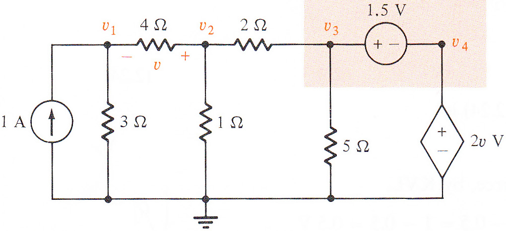
j,0,1,1
r3,0,1,3
r4,2,1,4
r1,2,0,1
r2,2,3,2
r5,3,0,5
ei,3,4,1.5
ed,4,0,2*vr4
The answers you want are in Results:
This is correct.
Bo2's Example 2.6
Open in app ↗Open in split view
Determine the voltages in all nodes.
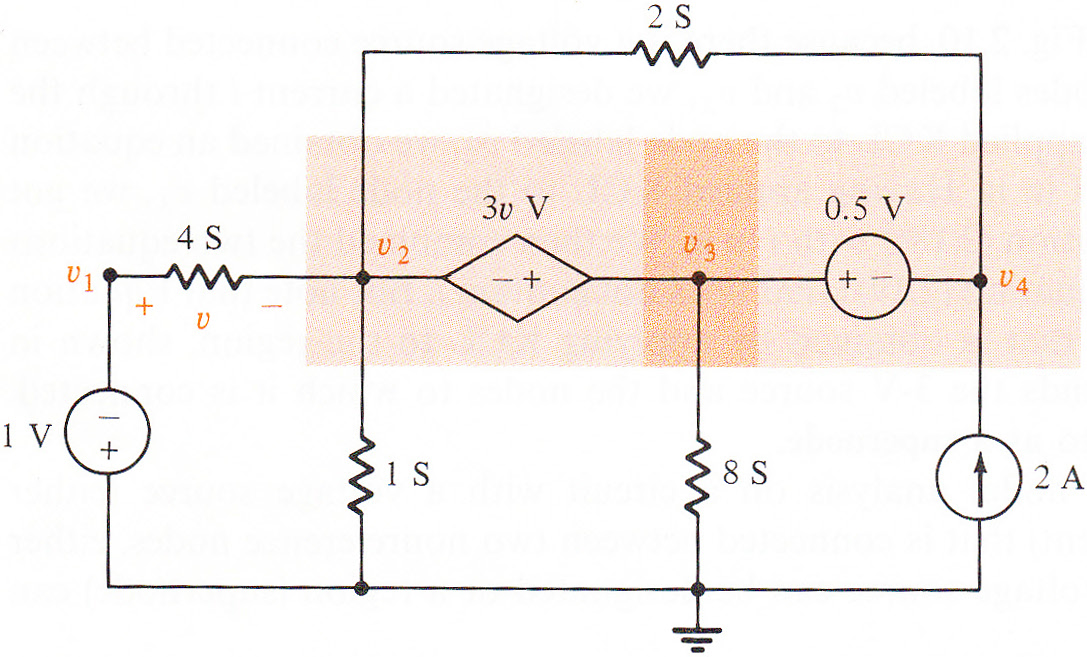
My solution:
e1,0,1,1
e2,3,4,.5
ed,3,2,3*vr4
j,0,4,2
r4,1,2,1/4
r1,2,0,1
r8,3,0,1/8
r2,2,4,1/2
The answers you want are in Results:
This is correct.
HK5's Drill Problem 1-12
Open in app ↗Open in split view
Find iA, iB and iC.
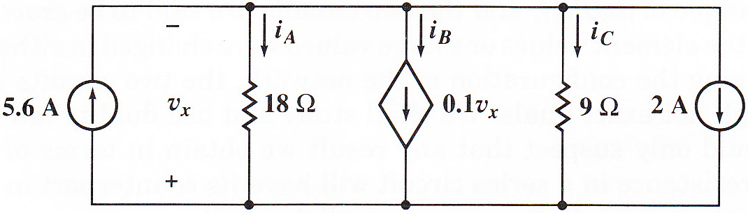
My solution:
jl,x,0,5.6
ra,0,x,18
jb,0,x,.1*vx
r9,0,x,9
jr,0,x,2
The answers you want are ira, ijb and ir9, in Results.
Here we use Rounding — approx to n digits, with n = 3.
The answers are:
This is correct.
Numerical-from-symbolic examples
Bo2's Drill Exercise 1.10
Open in app ↗Open in split view
Determine i, v, is and vs.

With one unknown value and one known solution, this problem is a job for Expert Mode.
Determine i, v, is and vs.
es,2,0,vs
jd,0,3,2*ir1
r7,0,1,7
r1,3,1,1
r3,3,2,3
r4,1,2,4
Set Analysis to DC — direct current. This one needs Enable Expert Mode ticked in the Expert Mode box; the equations and unknowns go in the fields it reveals.
The answers you want are ir1, vjd and vs, in Results; is is the opposite of ies.
In DC, add vr4=4 to the equations and vs to the unknowns, and run it. The answer is i=2, v=-9, is=-3 and vs=3. This is correct.
Bo2's Drill Exercise 1.11
Open in app ↗Open in split view
Determine i, v and vd. (Since all element values are known, the tip we are given by the book – namely, that the voltage drop in the 6Ω resistor is 1.5V – is totally superfluous.)

e,1,0,12
r1,1,2,1
r4,2,0,4
r10,2,3,10
r6,3,0,6
r2,3,4,2
j,4,0,vr10/15
The answers you want are vr10, ir2 and vj, in Results.
Here we use Rounding — approx to n digits, with n = 3.
The answer is i=.5, v=7.5 and vd=.5. This is correct.
Symbolic examples
TR5's Exercise 4.2
Open in app ↗Open in split view
Find vO and iO in terms of iS.
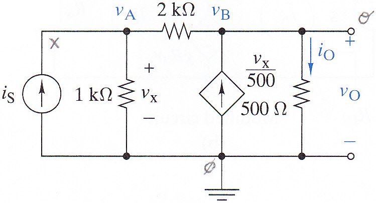
This is my solution.
ji,0,x,is
r1,x,0,1'k
r2,x,o,2'k
jd,0,o,vx/500
ro,o,0,500
The answers you want are vo and iro, in Results.
The answer is vO=1000 iS and iO=2 iS. This is correct.
TR5's Example 4.4
Open in app ↗Open in split view
Find vO and the equivalent resistance RIN, in terms of vS, when R1 is 50 Ω, R2 is 1 kΩ, R3 is 100 Ω, R4 is 5 kΩ and g is 100 mS (i.e. 100'm).
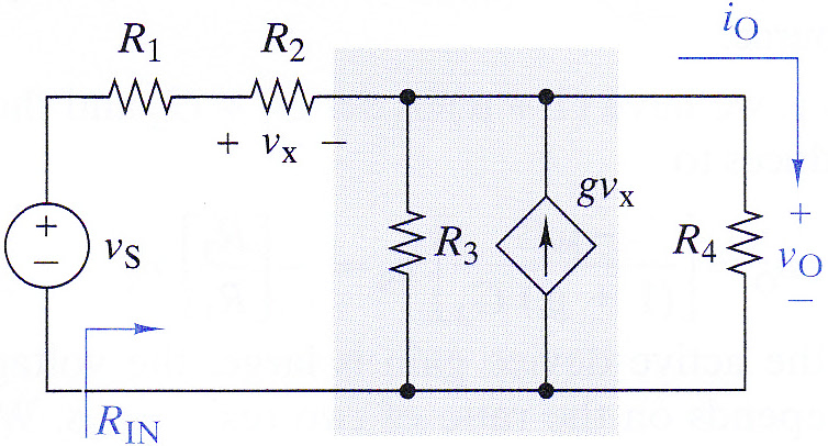
This is my solution.
e,1,0,vs
r1,1,2,50
r2,2,o,1'k
r3,o,0,100
r4,o,0,5'k
j,0,o,100'm*vr2
The answers you want are vo and re, in Results.
Here we use Rounding — approx to n digits, with n = 3.
The answer is vO=.904 vS and RIN = 10.95 kΩ. This is correct.
TR5's Figure 4-4
Open in app ↗Open in split view
Find the voltage drop, current, and power consumed by the 500Ω resistor, and the ratio of that power to that delivered by the independent source, all in terms of iS.
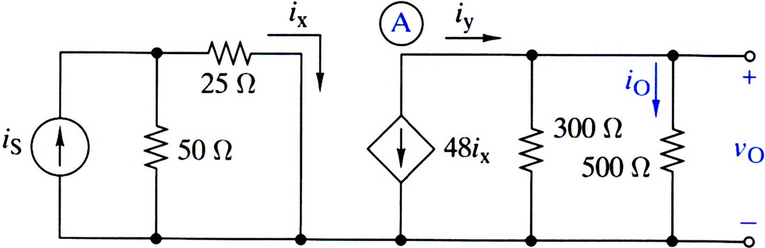
I have not labeled the nodes in the figure, so you can practice doing it. My solution:
js,0,1,is
r50,1,0,50
rx,1,0,25
jd,o,0,48*irx
r3,o,0,300
ro,o,0,500
The answers you want are iro, vo and pro, in Results.
Ask Evaluate for:
pro/(-pjs)The answers we get are correct: iO=-12is, vO=-6000is, pO=72000is2, and pO/pS=4320.
TR5's Example 4.1 (Symbolic)
Open in app ↗Open in split view
Find vO.
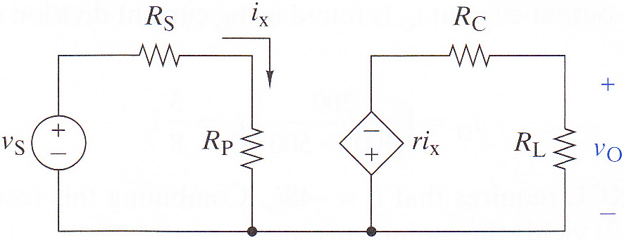
I did not label the nodes, so you can practice.
ei,1,0,vs
rs,1,2,rs
rx,2,0,rp
ed,0,3,r*irx
rc,3,o,rc
rl,o,0,rl
The answer you want is vo, in Results.
The answer, shown first below, is correct. The textbook's answer follows it.

Bo2's Example 1.11 (Symbolic)
Open in app ↗Open in split view
Determine v2.
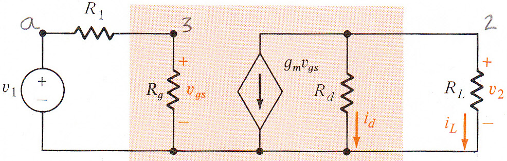
My solution. I named the source's value v1, as in the book, so no node may be called 1: its voltage would be v1 too. Using r1 as a value is fine.
e,a,0,v1
r1,a,3,r1
rg,3,0,rg
j,2,0,gm*vrg
rd,2,0,rd
rl,2,0,rl
The answer you want is v2, in Results.
The answer I got is shown first below (the textbook's follows it.)

TR5's Example 4-7 (Symbolic)
Open in app ↗Open in split view
Find RIN, i.e. the resistance as seen by the current source. My solution:

ji,0,a,is
re1,a,0,re1
jd,b,a,β*is
rl,b,0,rl
The answer you want is rji, in Results.
The answer we get — re1*(β+1) — is correct, as can be seen by comparing it to the textbook's answer.

TR5's Exercise 4.3 (Symbolic)
Open in app ↗Open in split view
Find vO, in terms of the value in the circuit. For resistors, use their conductance value.

This is my solution. We use µ as a constant in the dependent source. It is not confused with the SI prefix for micro because the prefix has an apostrophe.
ei,1,0,vs
ed,2,0,μ*(vrx)
r1,1,2,1/g1
r2,2,o,1/g2
rx,1,o,1/gx
rl,o,0,1/gl
The answer you want is vo, in Results.
The answer is correct; the textbook's follows it.

TR5's Example 4.5 (Symbolic)
Open in app ↗Open in split view
Find iB.

My solution is shown below.
e1,1,0,vcc
rb,1,b,rb
e2,e,b,vγ
re1,e,0,re1
rc,1,c,rc
j,c,e,β*irb
The answer you want is irb, in Results.
Compare my answer, first below, to the book's answer beneath it.
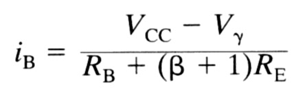
The answer given by the book uses variables with subscripts, which look very elegant. Symbolic answers can be made to read that way too, and the trick is one character: an underscore in a symbolic variable name puts what follows into a subscript. Underscores, and subscripts in your answers shows it on this very circuit — optional reading, and it changes no answer, only its look.
The last four problems show Symbulator at its DC best.
The Showing-off Problem (Expert)
Open in app ↗Open in split view
In 2013, I invented a problem to showcase how easy it is to describe dependent sources in Symbulator.
Question: Find positive values for Vs and Is that will result in 80W delivered by the VCCS and 0W dissipated in the CCVS.
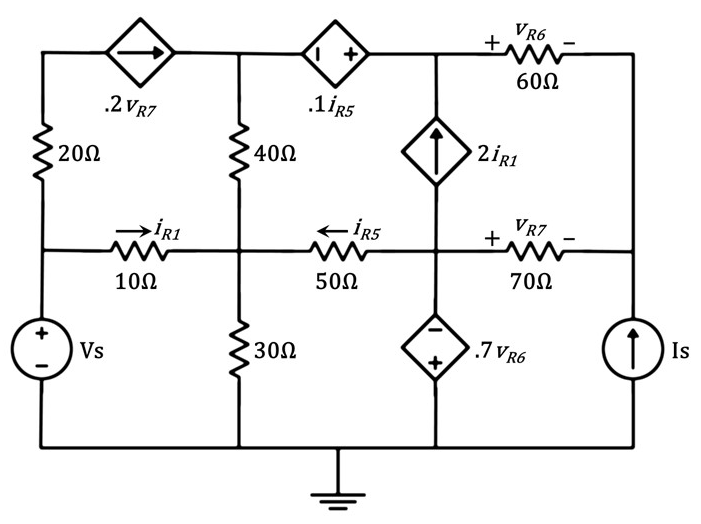
Use this circuit description and equations:
es,e,0,vs
js,0,d,is
r1,e,m,10
r2,a,e,20
r3,m,0,30
r4,b,m,40
r5,n,m,50
r6,c,d,60
r7,n,d,70
jd1,a,b,0.2*v_r7
ed2,c,b,0.1*i_r5
jd3,n,c,2*i_r1
ed4,0,n,0.7*v_r6
Symbulator reports the power consumed by each element, so delivering 80W is consuming −80W. In Expert Mode:
pjd1 = -80 and ped2 = 0vs, isThe problem asks for positive values, which is what the conditions are for: the two power equations are quadratic, so four solutions fit, and the conditions pick the one meant:
is > 0 and vs > 0Run it in DC, with Rounding at 4 significant digits. Everything comes back numerical: vs = 17.61 V and is = 0.3973 A.
The answers also show how the CCVS dissipates nothing: iR5 comes back exactly 0 A, and its voltage is 0.1 iR5, so the source itself is zero.