Lesson 9
Three-phase circuits
Learn to solve simple three-phase circuits in Y-Y, Y-Δ, Δ-Δ and Δ-Y configurations, both balanced and unbalanced, to find line and phase currents, voltages and complex power.
Last updated 2023-07-08
In this lesson you will learn to use Symbulator to solve simple three-phase systems, in their four basic configurations of wye-wye, wye-delta, delta-delta and delta-wye. We will see both balanced and unbalanced examples, where you are asked to find currents, voltages and complex power in the source, line and load.
9.1About solving three-phase circuits
Three-phase circuits can be tricky to solve in Symbulator, for several reasons. It is not always clear which node to use as ground. There are three times as many nodes as in an equivalent single-phase circuit. And sources in a delta array bring mathematical trouble: more unknowns than equations.
Symbulator does a great job on the simple three-phase circuits of a basic Circuits I / II textbook, and here we will see examples and one or two tricks. It would not be my tool of choice for anything larger: as circuits grow, the number of nodes quickly passes what your device can solve.
9.2Wye-Wye
Balanced wye-wye system
AS7's Examples 12.2 & 12.6
Open in app ↗Open in split view
Calculate the line currents in the three-wire Y-Y system. Determine the total average power, reactive power, and complex power absorbed at the source and at the load. Assume that the values given for the source are RMS.

AS7's Examples 12.2 and 12.6
Solution
Although not specified in the textbook, to get the answers they give we need to assume the values are RMS. One must describe the circuit carefully in the case of three-phase circuits, because it is very easy to make a mistake. Below is how I describe this one:
ea0,ag,0,(110∠0°)
eb0,bg,0,(110∠-120°)
ec0,cg,0,(110∠120°)
rat,ag,ad,5-2j
rbt,bg,bd,5-2j
rct,cg,cd,5-2j
ra0,ad,0,10+8j
rb0,bd,0,10+8j
rc0,cd,0,10+8j
AC, with RMS phasors ticked. Every value is already an impedance, so the frequency is asked for but never used.
Some observations about my description:
- Notice that I have specified the node at the centre of both Y's as node 0. This is something you can do only in the case of balanced Y-Y systems, not for other configurations and not for unbalanced systems.
- Since Symbulator does not differentiate between lower and upper case in names, nodes called a and A would be considered the same node. Instead, we use the names ag and ad, where the g reminds us a node is on the generation side and the d reminds us it is on the demand side.
Once the simulation is completed, we look in the results for the currents on the transmission lines:
Tick Show AC answers as polar phasors in Settings and each line impedance's current through reads straight off:
irat= 6.809∠-21.8° Airbt= 6.809∠-141.8° Airct= 6.809∠98.2° A
The complex power at the source is sea0+seb0+sec0, which gives −2086.2 − 834.5𝐢 VA. The real part is the average power absorbed by the source; since it is negative, the source is delivering an average power of 2086 W. The imaginary part is the reactive power: 834 var.
The complex power at the load is sra0+srb0+src0, which gives 1390.8 + 1112.6𝐢 VA. The load is consuming an average power of 1391 W and a reactive power of 1113 var.
Before we move on, try simulating this circuit with a different node as the centre of the load's Y array — call it d0, for the demand side. The voltage in that node evaluates to 0 V, because the system is balanced. That is why we could use 0 for both. In an unbalanced system we cannot.
Further wye-wye problems
AS7's Practice Problem 12.2 & 12.6
Open in app ↗Open in split view
Calculate the line voltages and the line currents. Also calculate the complex power at the source and at the load. Assume the source voltage is given as RMS.

AS7's Practice Problem 12.2 and 12.6
Solution
The textbook does not say so, but you only get its answers if you take the values as RMS.
There are three impedances in each line here: one inside the generator, one for the transmission line, and one for the load. The node names below say which is which — ag in the generator, as on the supply side, ad on the demand side.
ea0,ag,0,(120∠30°)
eb0,bg,0,(120∠-90°)
ec0,cg,0,(120∠150°)
rag,ag,as,.4+.3j
rbg,bg,bs,.4+.3j
rcg,cg,cs,.4+.3j
rat,as,ad,.6+.7j
rbt,bs,bd,.6+.7j
rct,cs,cd,.6+.7j
ra0,ad,0,24+19j
rb0,bd,0,24+19j
rc0,cd,0,24+19j
AC, with RMS phasors ticked. Every value is already an impedance, so the frequency is asked for but never used.
The question asks for the line voltages — the differences between the lines. For the answers the textbook wants, take these differences:
In Mini-Tools with aa:
aa(vag-vbg)= 207.8∠60.00° Vaa(vbg-vcg)= 207.8∠-60.00° Vaa(vcg-vag)= 207.8∠180.0° V
The line currents are the currents through the transmission-line impedances:
With polar phasors on, each transmission-line impedance's current through reads:
irat= 3.748∠-8.660° Airbt= 3.748∠-128.66° Airct= 3.748∠111.34° A
Finally the complex power. At the source:
Evaluate sea0+seb0+sec0, which gives -1054 − 842.9𝐢 VA.
Note this does not include the power lost in the source's own internal impedances, which you could add if you wanted them. At the load:
Evaluate sra0+srb0+src0, which gives 1012 + 800.8𝐢 VA.
All correct.
Unbalanced wye-wye system
The balanced case let you use node 0 for the centre of both wyes, because the voltage at the centre of the load is zero. Unbalanced, it is not — so the load needs a centre node of its own.
AS7's Example 12.10
Open in app ↗Open in split view
For the unbalanced circuit, find (a) the line currents, (b) the total complex power absorbed by the load, and (c) the total complex power absorbed by the source.

AS7's Example 12.10
Solution
The centre of the generator's wye is ground, and the centre of the load's wye is a node of its own, called n.
ea,a,0,(120∠0°)
eb,b,0,(120∠-120°)
ec,c,0,(120∠120°)
ra,a,n,5j
rb,b,n,10
rc,c,n,-10j
AC, with RMS phasors ticked.
The three line currents read 56.78∠0°, 25.46∠135.0° and 42.76∠-155.1° A. The complex powers in the load are 16120𝐢, 6480 and -18280𝐢 VA, and in the three sources -6814, 790.6 − 2951𝐢 and -456.5 + 5111𝐢 VA.
All correct. Two things are worth checking for yourself. Complex power is conserved, so sea+seb+sec+sra+srb+src evaluates to zero. And the voltage at the centre of the load is not zero, as it was in the balanced case — vn is 120.0 − 283.9𝐢 V.
AS7's Example 12.9
Open in app ↗Open in split view
The unbalanced Y-load has balanced voltages of 100 V in the acb sequence. Calculate the line currents and the neutral current. Take ZA = 15 Ω, ZB = 10 + j5 Ω and ZC = 6 − j8 Ω.
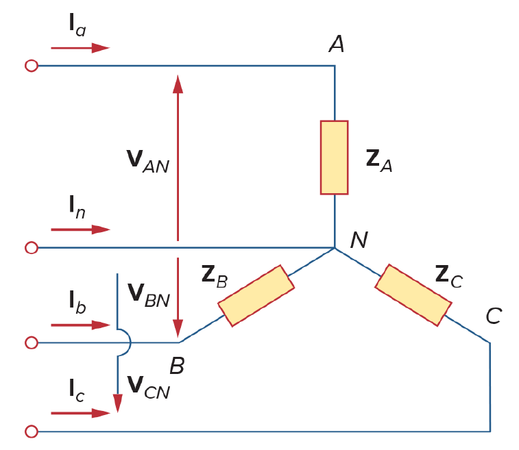
AS7's Example 12.9
Solution
Two things differ from the last one. The source values are not RMS this time. And there is a neutral line joining the centre of the load to the centre of the source, which you describe as a short circuit — an s element, which takes just a name and two nodes.
Note also the angles: this is the acb sequence, so they run the other way round.
ea,a,0,(100∠0°)
eb,b,0,(100∠120°)
ec,c,0,(100∠-120°)
sn,0,n
ra,a,n,15
rb,b,n,10+5j
rc,c,n,6-8j
AC, with RMS phasors left unticked this time.
The three line currents read 6.667∠0°, 8.944∠93.43° and 10.00∠-66.87° A, and the neutral current 10.06∠178.5° A.
All four are correct. The neutral carries a current precisely because the load is unbalanced; in the balanced case it would be zero, which is why a balanced three-wire system needs no neutral at all.
9.3Wye-Delta
A wye source feeding a delta load. The source still has a centre to use as ground; the load does not, which is the only new thing here.
Balanced
AS7's Example 12.3
Open in app ↗Open in split view
For the balanced Y-Δ circuit, find the phase currents and the line currents.

AS7's Example 12.3
Solution
Nothing says these values are RMS, so leave the convention alone — the question asks for no powers, so it makes no difference either way. The three sources get the angles of the abc sequence.
ea0,a,0,(100∠10°)
eb0,b,0,(100∠-110°)
ec0,c,0,(100∠130°)
rab,a,b,8+4j
rca,c,a,8+4j
rbc,b,c,8+4j
The phase currents are the currents in the three load impedances:
aa(irab), aa(irbc) and aa(irca) read 19.36∠13.43°, 19.36∠-106.57° and 19.36∠133.43° A.
The line currents are the currents the sources deliver, which is the opposite of the current through each source element:
aa(-iea0), aa(-ieb0) and aa(-iec0) read 33.54∠-16.57°, 33.54∠-136.57° and 33.54∠103.43° A.
Both sets are correct, and they show the relationship you would expect of a delta load: the line current is √3 times the phase current, and lags it by 30°.
AS7's Example 12.11
Open in app ↗Open in split view
For the balanced Y-Δ circuit, find the line current IaA, the phase voltage VAB, and the phase current IAC. The source frequency is 60 Hz.
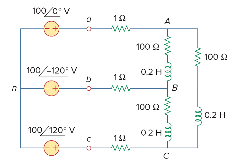
AS7's Example 12.11
Solution
This one has line impedances, so each source reaches the load through a resistor, and the load's three nodes are separate from the source's three.
ea1,na1,0,100
eb1,nb1,0,(100∠-120°)
ec1,nc1,0,(100∠120°)
raa,na1,na2,1
rbb,nb1,nb2,1
rcc,nc1,nc2,1
rac,na2,nc2,100+24*pi*j
rcb,nc2,nb2,100+24*pi*j
rba,nb2,na2,100+24*pi*j
The line current is the current in one of the line resistors, and the phase voltage is the difference between two load nodes:
aa(iraa) reads 2.35∠-36.2° A and aa(vna2-vnb2) reads 169.94∠30.81° V. Both are correct.
For the phase current, aa(irac) reads 1.357∠-66.2° A.
Unbalanced
If you find a simple unbalanced wye-delta problem, let me know.
9.4Delta-Delta
Until now, choosing a ground node was easy: the centre of the wye of sources. A delta has no centre, which is the first problem. It is solved by picking one of the delta's own nodes on the generator side and calling it 0.
The second problem is subtler, and it is not Symbulator's alone — SPICE-like simulators dislike it too. A triangle of three voltage sources cannot be solved. The third source adds no information, because the first two already fix the voltages at all three nodes, but it does add an unknown: the current through it. Drop the redundant equation and the system has one unknown too many.
Balanced
AS7's Example 12.4
Open in app ↗Open in split view
A balanced Δ-connected load of 20 − j15 Ω is fed by a Δ-connected, positive-sequence generator with Vab = 330∠0° V. Find the phase currents of the load and the line currents.

AS7's Example 12.4
Solution
Node c becomes ground, so the source left out is the one opposite it. To read the line currents we add three shorts to act as the lines.
e0a,0,ag,(330∠120°)
eb0,bg,0,(330∠-120°)
sat,ag,ad
sbt,bg,bd
sct,0,cd
rab,ad,bd,20-15j
rbc,bd,cd,20-15j
rca,cd,ad,20-15j
The line currents are the currents through the shorts:
aa(isat), aa(isbt) and aa(isct) read 22.86∠6.87°, 22.86∠-113.13° and 22.86∠126.87° A.
Correct.
Unbalanced
Nothing changes in the method. The load impedances simply differ, and the answers stop being three copies of one another.
AS7's Practice Problem 12.9
Open in app ↗Open in split view
The unbalanced Δ-load is supplied by balanced line-to-line voltages of 440 V in positive sequence. Find the line currents, taking Vab as the reference.

AS7's Practice Problem 12.9
Solution
e0a,0,ag,(440∠120°)
eb0,bg,0,(440∠-120°)
sla,ag,ad
slb,bg,bd
slc,0,cd
rab,ad,bd,10-5j
rbc,bd,cd,16
rca,cd,ad,8+6jaa(isla), aa(islb) and aa(islc) read 39.71∠-41.07°, 64.12∠-139.77° and 70.13∠74.27° A.
Correct — and unlike the balanced case, all three differ in magnitude as well as angle.
AS7's Practice Problem 12.10
Open in app ↗Open in split view
Find the line currents in the unbalanced three-phase circuit, and the real power absorbed by the load.
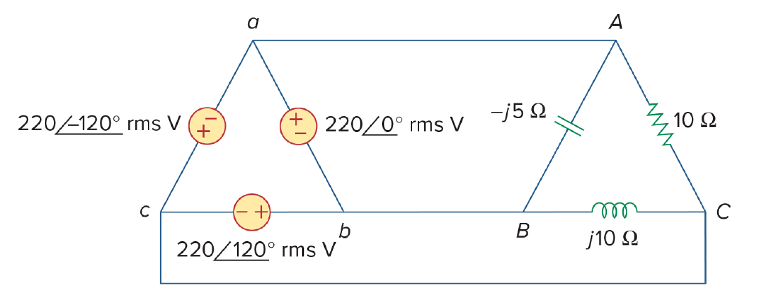
AS7's Practice Problem 12.10
Solution
These values are RMS, so tick RMS phasors in Settings — this one does ask for power.
e0a,0,ag,(220∠-120°)
eb0,bg,0,(220∠120°)
sla,ag,ad
slb,bg,bd
slc,0,cd
rab,ad,bd,-5j
rbc,bd,cd,10j
rca,cd,ad,10
The three line currents read 64.00∠80.1°, 38.11∠-60° and 42.50∠-135° A.
For the power, add the three loads' consumption in Evaluate:
prca+prab+prbcIt gives 4840 W.
Correct.
AS7's Example 12.12
Open in app ↗Open in split view
For the unbalanced Δ-Δ circuit, find the generator current Iab, the line current IbB and the phase current IBC.
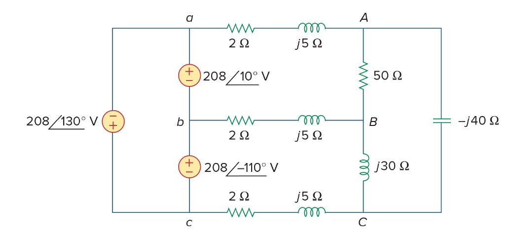
AS7's Example 12.12
Solution
Two of the three are ordinary element currents. The first — the current inside the generator — is the awkward one, and it is dealt with after them.
e0a,0,ag,(208∠130°)
eb0,bg,0,(208∠-110°)
rla,ag,ad,2+5j
rlb,bg,bd,2+5j
rlc,0,cd,2+5j
rab,ad,bd,50
rbc,bd,cd,30j
rca,cd,ad,-40j
Find equivalent is not needed here — a plain AC solve gives both. aa(irlb) reads 9.106∠168.48° A and aa(irbc) reads 5.500∠172.47° A, matching the printed answers.
The remaining answer, the generator current, is trickier. They ask for the current in the source we did not simulate — and even for one of the two we did have, we could not trust it, since the real circuit uses three.
Now, I tried something, and I think I got lucky, because I got the answer the book gives. This is what I tried:
-(ie0a+ieb0)/3 in Mini-Tools with aa, which takes an expression as readily as a name and answers with the magnitude and the angle.
What I thought was: the current coming out of the two sources in my simulation would, in reality, come out of three. So adding those two currents and dividing by three may approximate the current out of one source. I am confident that holds in a balanced circuit. This one is not balanced, but it was the best I had. So I tried it.
5.959∠-177.18° A
And it worked. That is the answer in the book.
9.5Delta-Wye
The Δ-Y is the platypus of three-phase systems. The sensible route is usually to convert the Δ source into an equivalent Y and solve it as a Y-Y — and if you are doing this by hand, do that.
Inside Symbulator there is another way: make the centre of the wye load the ground node, and describe the delta source with two sources as before.
Balanced
AS7's Example 12.5
Open in app ↗Open in split view
For the balanced Δ-Y circuit, find the line currents.

AS7's Example 12.5
Solution
eca,c,a,(210∠120°)
ebc,b,c,(210∠-120°)
ra,a,0,40+25j
rb,b,0,40+25j
rc,c,0,40+25j
Node 0 here is the centre of the load's wye, not a node of the source at all.
aa(ira), aa(irb) and aa(irc) read 2.570∠-62.01°, 2.570∠177.99° and 2.570∠57.99° A.
Correct — balanced, so three equal magnitudes 120° apart.
Unbalanced
If you find a simple unbalanced delta-wye problem, let me know.