
Lesson 5
Operational amplifiers
Learn how to describe an ideal operational amplifier (Op Amp) using the o element. And practice what you learn in a variety of solved op-amp problems, both easy and hard.
Last updated 2023-07-08
In this lesson, you will learn how to describe an ideal operational amplifier — also called an Op Amp — using the o element. And you will practise what you learn in a variety of solved op-amp problems, both easy and hard.
5.1How to describe an ideal operational amplifier
There are many types of operational amplifiers. Symbulator can simulate the ideal, linear type.
What answers do you get
For each ideal op amp in a circuit, Symbulator will store the following answers:
- The current through the output node, flowing from the output node outwards. For an op amp called o, that is
io. - The power consumed by the visible part of the op amp. For an op amp called o2,
po2; the power delivered is the negative of that. - And, as with every element's nodes, the voltage of each of its nodes with reference to ground. For node o,
vo.
Livin' on the edge
Since I was born to be bad, I like to play with node names to get the answers as close to the book as possible. So do not be surprised if I call one op amp "o" and name its output node "o" as well. That way I can ask for vo and io and get the output voltage and current. But realise this: vo asks for the voltage in node o, while in io the o stands for the element o.
You, too, can be bad to the bone, and live dangerously with your node naming, as long as you anticipate what variables Symbulator will create to store the answers. I tell you this because there are limits to what you can get away with.
For example, when naming nodes, remember that for a node called #, Symbulator creates a variable v# for its voltage. So never give a node the same name as an element that has a voltage drop of its own: r, e, j, c, l. If in doubt, play it safe and give every node a name of its own, different from any other node and from any element.
In this example, we got away with it because op amps are not that type of element. Symbulator does not save a voltage drop for op amps in a variable called vo, so there is no problem having a node called o in the same circuit.
Bo2's Drill Exercise 3.2
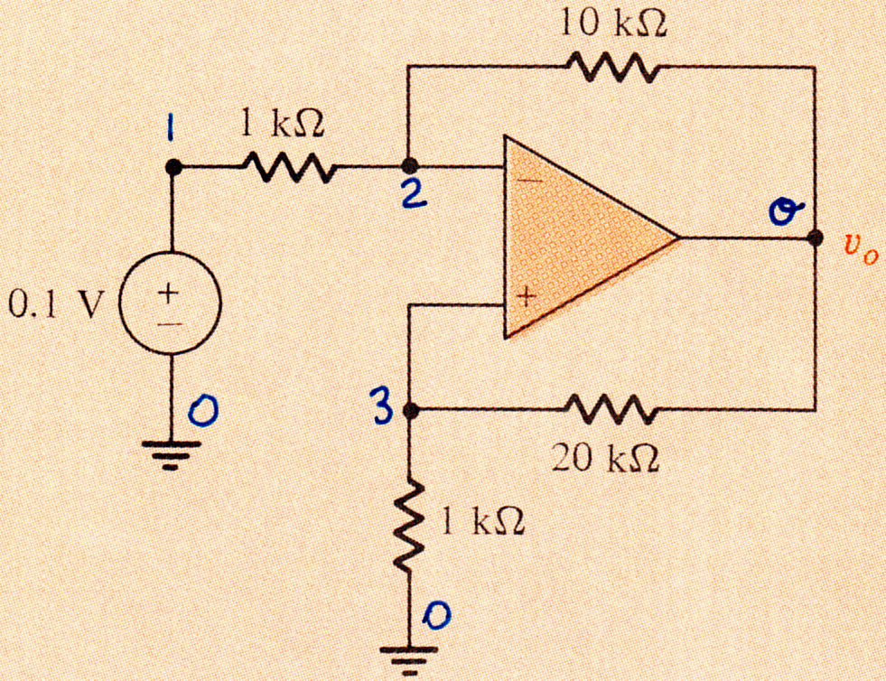
For the op-amp circuit shown, find vo and the power absorbed by the op amp.
Bo2's Drill Exercise 3.2
Solution
My solution:
s\dc("e,1,0,.1:r12,1,2,1'k:r2o,2,o,10'k:r30,3,0,1'k:r3o,3,o,20'k:o,3,2,o")We ask for the values of the variables vo and po:
{vo,po}{–2.1, –.00063}Which are correct. The voltage in node o is –2.1 V, and the op amp is absorbing –.63 mW, which is to say it is delivering .63 mW of power to the circuit.
5.2Instructive Op Amp examples
Solved Op Amp problems
Bo2's Drill Exercise 3.11 (Thévenin)
Find the Thévenin equivalent.

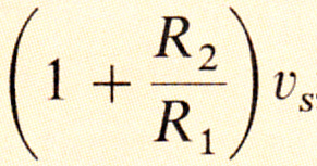
s\th("e,1,0,vs:r1,2,0,r1:r2,2,3,r2:o,1,2,3",3,0)The th script tells us it found the Thévenin voltage, but could not find the Norton current. This is not a surprise, since an ideal op amp has zero output resistance and a fixed voltage, an infinite current when short-circuited. So the Thévenin equivalent is given by VTH and no resistance (or REQ = 0Ω). Evaluating vth results in
((r1+r2) vs)/r1
This is correct, as can be seen by comparing it to the book's answer, shown below.
The Thévenin resistance, as explained above, is 0Ω.
AS2's Example 5.2
Find vo and io.
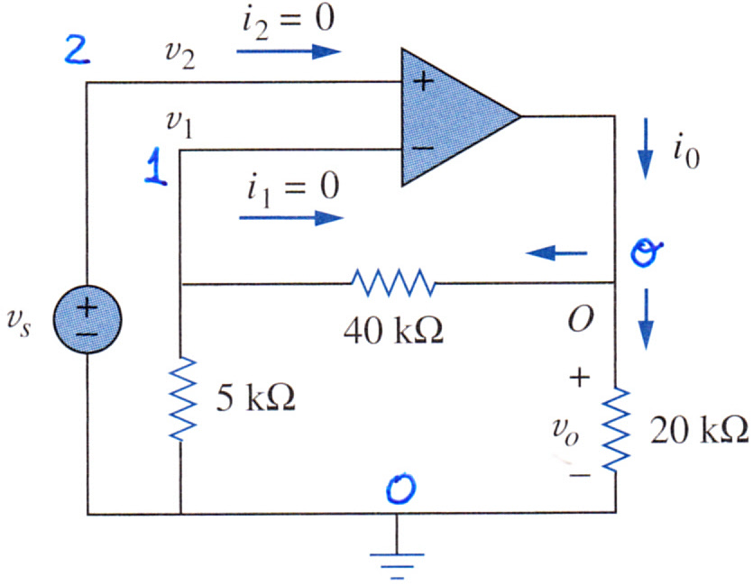
s\dc("e,2,0,1.:r5,1,0,5'k:r4,1,o,40'k:r2,o,0,20'k:o,2,1,o"):{vo,io}The answer, {9.,.00065}, is correct: vo is 9V and io is 0.65mA
Bo2's Figure 3.3 (Inverting)
Find the gain of the overall circuit, vo/vS.
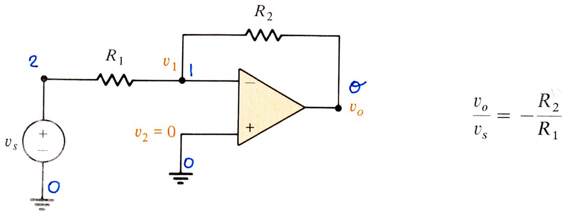
s\dc("e,2,0,vs:r1,2,1,r1:r2,1,o,r2:o,1,0,o"):vo/vsWe get -r2/r1, which is correct, as can be seen in the book's answer above.
AS2's Figure 5.10 (Inverting)
Find vo.

s\dc("e,2,0,vi:r1,2,1,r1:rf,1,o,rf:o,0,1,o"):voThis problem is almost identical to the one above. The answer we get is correct:
-(rf/r1)vi
AS2's Example 5.3 (Inverting)
If vi is 0.5V, calculate the output voltage vo and the current in the 10 kΩ resistor.

s\dc("e,2,0,.5:r1,2,1,10'k:rf,1,o,25'k:o,0,1,o"):{vo,ir1}The answer, {-1.25, 5e-5}, is correct.
TR5's Exercise 4-11 (Inverting)
Find vO when vS is 2V, -4V and 6V. Notice the output of the op amp is limited to ±15V.

This may be the only non-linear problem you will see in this book, because I solved it before I realized it included the ±15V constraint. But anyway, here it goes.
s\dc("e,1,0,vs:r1,1,2,10'k:r2,2,o,33'k:o,0,2,o"):
{vo|vs=2.,vo|vs=–4.,vo|vs=6.}
The answer, {-6.6,13.2,-19.8}, is correct within the linear realm, but since the output is constrained to no more than 15V or less than -15V, the answer is vO=-15V for vS = 6V.
AS2's Practice Problem 5.3 (Inverting)
Find the output voltage of the op amp (i.e. vo) and calculate the current through the feedback resistor (i.e. the 15 kΩ resistor).
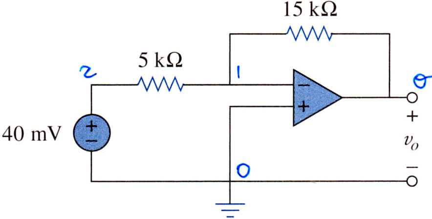
My answer: Notice we used the m for milli in the value of the voltage source.
s\dc("e,2,0,40'm:r1,2,1,5'k:rf,1,o,15'k:o,0,1,o"):approx({vo,irf})The answer, {-.12, 8e-6}, is correct.
AS2's Example 5.4 (Inverting)
Determine vo.

s\dc("e6,1,0,6:r1,1,a,20'k:e2,b,0,2:rf,a,o,40'k:o,a,b,o"):voThe answer, -6, is correct.
TR5's Example 4-14 (Inverting)
Find the input-output relationship of the circuit.
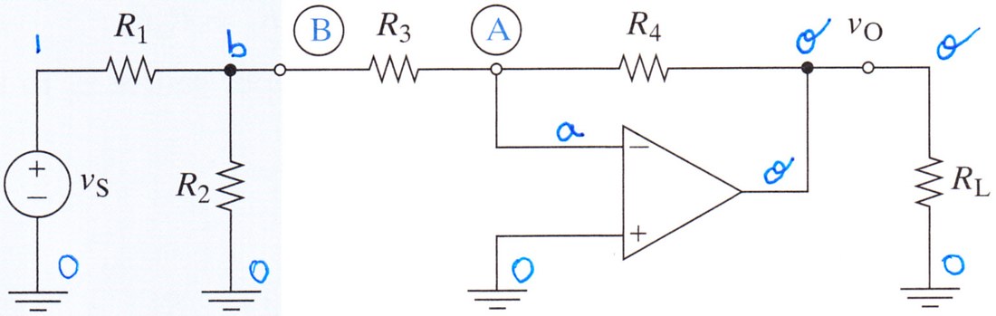
The 'formal' way to symbulate this circuit would be as described below.
s\dc("e,1,0,vs:r1,1,b,r1:r2,b,0,r2:r3,b,a,r3:r4,a,o,r4:o,0,a,o:rl,o,0,rl")However, since we are only interested in the ratio of the input to the output, a smarter (and faster – as in 49 seconds instead of 55 seconds) way to symbulate it is this:
s\dc("e,1,0,1:r1,1,b,r1:r2,b,0,r2:r3,b,a,r3:r4,a,o,r4:o,0,a,o:rl,o,0,1")When we evaluate vo/v1, both approaches get the same answer:
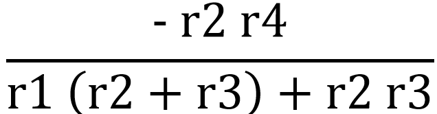
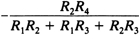
which is correct, as can be seen by comparing it to the book's answer.
AS2's Practice Problem 5.4a (Transresistance)
This is a current-to-voltage converter, also called a transresistance amplifier. Find vo/iS.

s\dc("j,0,1,is:r,1,o,r:o,0,1,o"):vo/isThe answer, -r, is correct.
AS2's Practice Problem 5.4b (Transresistance)
This is another transresistance amplifier. Again, find vo/iS.
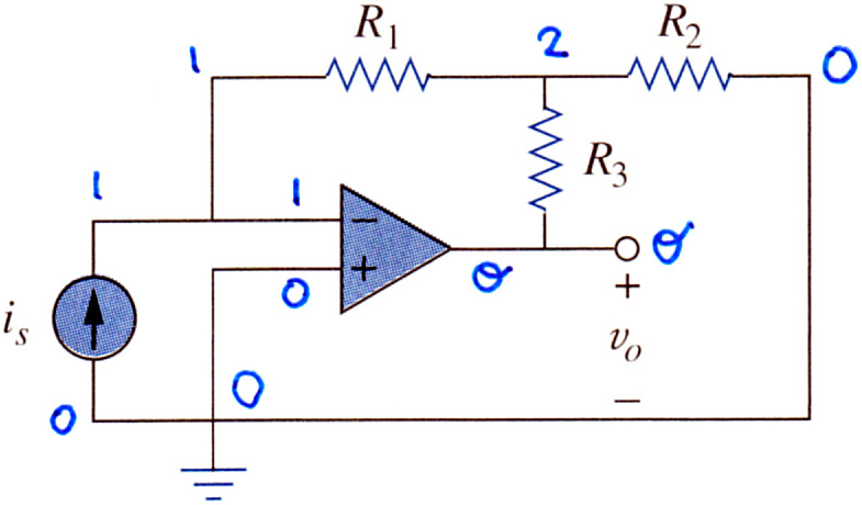
s\dc("j,0,1,is:r1,1,2,r1:r2,2,0,r2:r3,2,o,r3:o,0,1,o")Asking:
expand(vo/is)
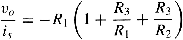
gets -r1*r3/r2-r1-r3, which is equivalent to the book's answer.
Bo2's Example 3.1 (Non-Inverting Amplifier)
Find vo/v1.
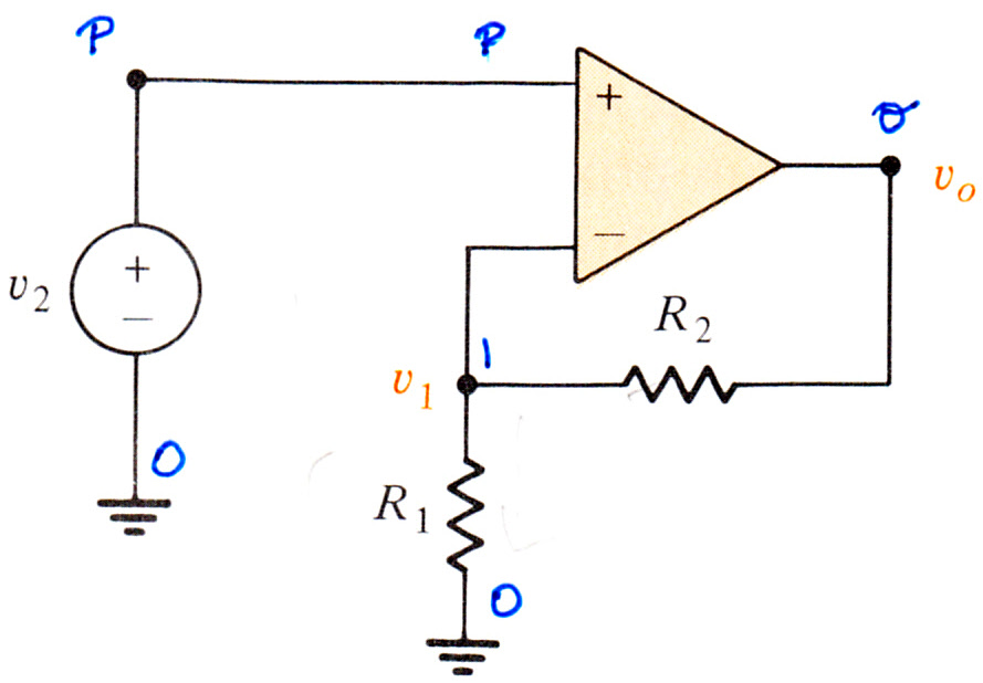
s\dc("e,p,0,v2:r1,1,0,r1:r2,1,o,r2:o,p,1,o"):vo/v1We get \(1 + \frac{r_{2}}{r_{1}}\), which is correct.
AS2's Figure 5.16 (Non-Inverting Amplifier)
Find vo.

s\dc("e,2,0,vi:r1,0,1,r1:rf,1,o,rf:o,2,1,o"):voWe get the right answer (below), an expression equivalent to the book's answer.
TR5's Example 4-13 (Non-Inverting Amplifier)
Find Vo/Vs.

We can solve this problem in one simulation, as shown below.
s\dc("e,1,0,vs:r1,1,2,r1:r2,2,0,r2:o,2,3,o:r3,o,3,r3:r4,3,0,r4"):vo/vsWe get
which is correct, as can be seen by comparing it to the book's answer.
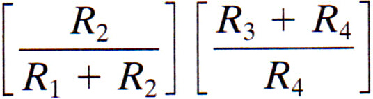
We can also solve it in stages, as shown below. First, simulate the left half.
s\dc("e,1,0,vs:r1,1,2,r1:r2,2,0,r2"):v2/vsWe get
which is correct for this part. Then, simulate the right half.
s\dc("e,2,0,1:o,2,3,o:r3,o,3,r3:r4,3,0,r4"):vo/v2We get
which is correct for this part. The product of these two partial answers produces the same expression shown above after the big simulation, and is the right answer.
AS2's Figure 5.17 (Voltage Follower)
Find vo.
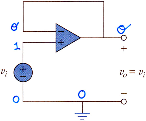
s\dc("e,1,0,vi:o,1,o,o"):voThe answer, vi, is correct.
TR5's Figure 4-32 (Voltage Follower)


Alright, so first we simulate the (b) circuit, to find its maximum power and load power:
s\th("e,1,0,1.5:rs,1,2,2'k",2,0):{pmax,prL|L=1000}The answers we get, {2.8125e-4,2.5e-4}, are correct. Now we simulate the (a) circuit.
s\dc("e,1,0,1.5:rs,1,2,2'k:o,2,o,o:rl,o,0,1'k"):prLThe answer, .00225, is correct. The apparent paradox — the load in (a) drawing more power than the source in (b) seems able to provide — evaporates once we remember that the ideal op amp in the schematic is only part of the truth: the real one has its own source of power, which makes up the difference.
AS2's Example 5.5 (Inverting)
Find vo.

s\dc("e,1,0,6:r4,1,a,4'k:r10,a,o,10'k:e4,b,0,4:o,b,a,o"):voThe answer, -1, is correct.
AS2's Practice Problem 5.5 (Non-Inverting)
Calculate vo.

s\dc("e,1,0,3:r4,1,2,4'k:r8,2,0,8'k:r2,3,0,2'k:r5,3,o,5'k:o,2,3,o")The answer for vo, 7, is correct.
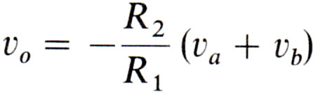
Bo2's Example 3.2 (Adder or Summing)
Find vo.
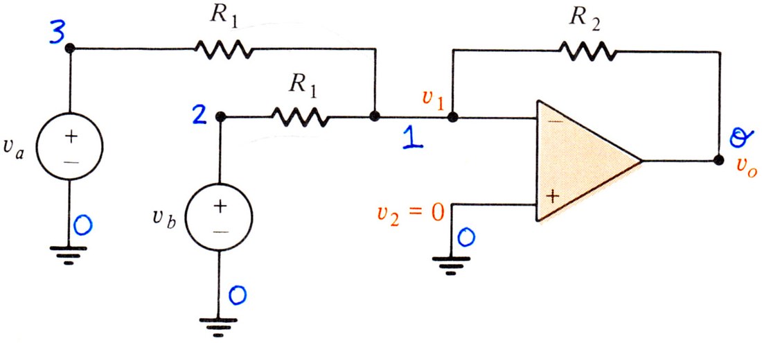
s\dc("ea,3,0,va:eb,2,0,vb:r31,3,1,r1:r21,2,1,r1:r1o,1,o,r2:o,0,1,o"):vo-(r2/r1)(va+vb)
which is correct, as can be seen by comparing it to the book's answer.
AS2's Figure 5.21 (Adder or Summing)
Find vo.

s\dc("e1,b,0,v1:e2,c,0,v2:e3,d,0,v3:r1,b,a,r1:
r2,c,a,r2:r3,d,a,r3:rf,a,o,rf:o,0,a,o"):expand(vo)
-rf v1/r1 - rf v2/r2 - rf v3/r3
which is correct, as can be seen by comparing it to the book's answer.

AS2's Example 5.6 (Adder or Summing)
Find vo and io.

s\dc("e1,1,0,1:e2,2,0,2:r1,2,a,5'k:
r2,1,a,2.5'k:r3,a,o,10'k:r4,o,0,2'k:o,0,a,o"):{vo,io}
The answer, {-8.,-.0048}, is correct. Notice a current of 4.8mA is going into the op amp.
AS2's Practice Problem 5.6 (Adder or Summing)
Find vo and io.
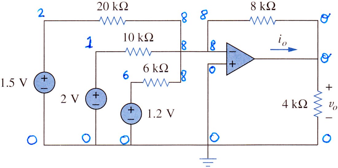
s\dc("e2,2,0,1.5:e1,1,0,2:e6,6,0,1.2:r2,2,8,20'k:
r1,1,8,10'k:r6,6,8,6'k:r8,8,o,8'k:r4,o,0,4'k:o,0,8,o"):{vo,io}
The answer, {-3.8,-.001425}, is correct. Again, the current is going into the op amp.
Bo2's Drill Exercise 3.3 (Difference or Differential)


s\dc("ea,4,0,va:eb,3,0,vb:r1,4,1,r1:r2,1,o,r2:
r3,3,2,r1:r4,2,0,r2:o,2,1,o")
Evaluating vo we get the correct answer, equivalent to the book's answer above.
((vb-va) r2)/r1
TR5's Exercise 4-13 (Difference or Differential)
Find vo.

s\dc("e1,3,0,v1:e2,4,0,v2:r1,3,5,10'k:r2,4,6,10'k:
r3,5,o,40'k:r4,6,0,15'k:o,6,5,o")
Evaluating vo we get 3 v2 − 4 v1, which is the correct answer.
AS2's Figure 5.24 (Difference or Differential)
Find vo. (And keep it in the memory, for you will use it in the next three problems.)

s\dc("e1,d,0,v1:e2,c,0,v2:r1,d,a,r1:r3,c,b,r3:
r2,a,o,r2:r4,b,0,r4:o,b,a,o"):voThis expression is equivalent to the book's answer.

AS2's Figure 5.24 (Subtractor)
For the same circuit of the previous problem, find vo when R1=R2 and R3=R4.
Since we already have the expression for vo stored in the memory, we only do this:
expand(vo)|r2=r1 and r3=r4The answer we get, v2-v1, is correct.
AS2's Example 5.7 (Difference or Differential)
Design an op amp circuit with inputs v1 and v2 such that vo = -5v1 + 3v2.
My solution follows. The problem statement is a fancy way of saying: for the circuit of the previous problem, find the resistor values that give an output vo = -5v1 + 3v2. Not strictly a Symbulator problem, but it shows how Symbulator fits into design problems.
First we take that part of vo that is a factor of v1, and make it equal to -5. Thus:
Define v1=1:Define v2=0:expand(vo)=–5We get -r2/r1=-5. Now make that part of vo that is a factor of v2 equal to 3. Thus:
Define v1=0:Define v2=1:expand(vo)=3We get r2*r4/(r1*(r3+r4))+r4/(r3+r4)=3 Now, since you have two equations, you can solve for two unknowns. Of the four resistors you get to choose, two can be whatever you want. The book recommends R1 = 10 kΩ and R3 = 20 kΩ. Now let's find R2 and R4.
solve(ans(1) and ans(2),{r2,r4})|r1=10000 and r3=20000The expression above assumes that ans(1) and ans(2) are pointing to the two equations we found before. We get r2=50000 and r4=20000. This is correct.
Now, if this problem was part of a test, I'd like to verify that the answer is correct. To confirm this, simulate the circuit using the four values given above for the resistors.
s\dc("e1,d,0,v1:e2,c,0,v2:r1,d,a,10'k:
r3,c,b,20'k:r2,a,o,50'k:r4,b,0,20'k:o,b,a,o")
Evaluating vo gives us the desired output, 3*v2-5*v1. The resistor values are correct.
AS2's Practice Problem 5.7 (Difference or Differential)
Design a difference amplifier with gain 4.
My solution follows. Again the statement is a fancy way of saying: for the circuit of the previous problem, find the resistor values that give an output vo = 4 (v2-v1), that is, -4v1 + 4v2. Same as before.
Define v1=1:Define v2=0:vo=–4Define v1=0:Define v2=1:expand(vo)=4This time the book asks that you use R1 = 10 kΩ and R3 = 10 kΩ. So we do that.
solve(ans(1) and ans(2),{r2,r4})|r1=10000 and r3=10000We get r2=40000 and r4=40000, the correct values for the remaining resistors.
AS2's Practice Problem 5.8 (Instrumentation)
Find io.

s\dc("e1,1,0,8.:e2,2,0,8.01:o1,1,3,3:o2,2,4,4:r1,3,5,20'k:
r2,4,6,20'k:r3,5,o,40'k:r4,6,0,40'k:o3,6,5,o:r5,o,0,10'k"):ir5
In the schematic, the current io corresponds to ir5. The answer, 2e-6, is correct.
Bo2's Example 3.3 (Cascade)
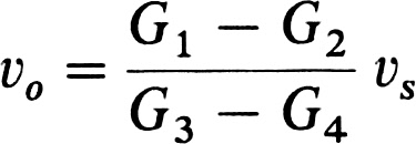
Find vo in terms of the conductances and the applied voltage vS.

s\dc("e,1,0,vs:r12,1,2,1/g1:r14,1,4,1/g2:r4o,4,o,1/g3:
r2o,2,o,1/g4:r23,2,3,1/g:r34,3,4,1/g:o1,0,2,3:o2,0,4,o")
Evaluating vo we get:
((g1-g2) vs)/(g3-g4)
which is correct, as can be seen by comparing it to the book's answer.
Bo2's Drill Exercise 3.4 (Cascade)


s\dc("e,1,0,vs:r1,2,o,1/1:r2,1,2,1/2:r3,2,3,1/3:
r4,4,0,1/4:r5,4,o,1/5:o1,0,2,3:o2,3,4,o")
Evaluating vo we get: -.75 vs, which is correct.
AS2's Example 5.9 (Cascade)
Find vo and io.
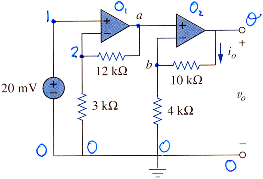
s\dc("e,1,0,20'm:o1,1,2,a:o2,a,b,o:ro,o,b,10'k:
r4,b,0,4'k:r2,a,2,12'k:r3,2,0,3'k")
Evaluating approx({vo,iro}) we get the answer, {.35,2.5e-5}. This is correct.
AS2's Practice Problem 5.9 (Cascade)
Determine vo and io.
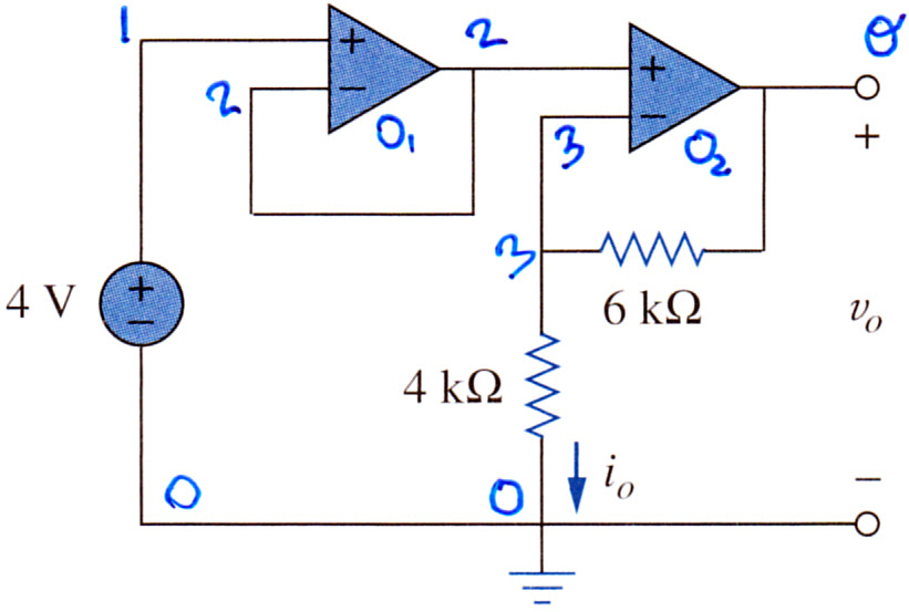
s\dc("e,1,0,4:o1,1,2,2:o2,2,3,o:ro,3,0,4'k:r6,3,o,6'k"):{vo,iro}The answer, {10,1/1000}, is correct. To say a 1/1000 A current is the same as 1mA.
AS2's Practice Problem 5.10 (Cascade)
If v1 = 2V and v2 = 1.5V, find vo in the circuit.

s\dc("e1,1,0,2:e2,2,0,1.5:o1,1,3,3:r1,2,5,10'k:r2,3,6,20'k:
r5,5,4,50'k:o2,0,5,4:r3,6,4,30'k:r6,6,o,60'k:o3,0,6,o"):vo
The answer, 9, is correct.
TR5's Example 4-16 (Cascade)
Derive an expression for vo in terms of the two inputs.
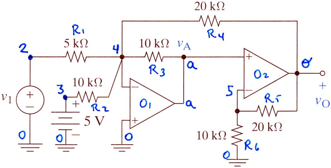
s\dc("e1,2,0,v1:e5,3,0,5:r1,2,4,5'k:r2,3,4,10'k:o1,0,4,a:r3,4,a,10'k:
r4,4,o,20'k:o2,a,5,o:r5,5,o,20'k:r6,5,0,10'k"):expand(approx(vo))
The answer, -2.4 v1 − 6, is correct.
TR5's Exercise 4-14 (Cascade)
Derive an expression for vo in terms of the inputs v1 and v2.
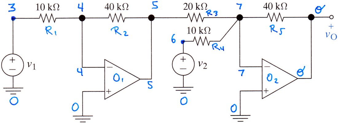
s\dc("e1,3,0,v1:r1,3,4,10'k:o1,0,4,5:r2,4,5,40'k:r3,5,7,20'k:
e2,6,0,v2:r4,6,7,10'k:r5,7,o,40'k:o2,0,7,o"):expand(vo)
The answer, 8 v1 – 4 v2, is correct.
AS2's Example 5.10 (Cascade)
If v1 = 1V and v2 = 2V, find vo in the circuit.
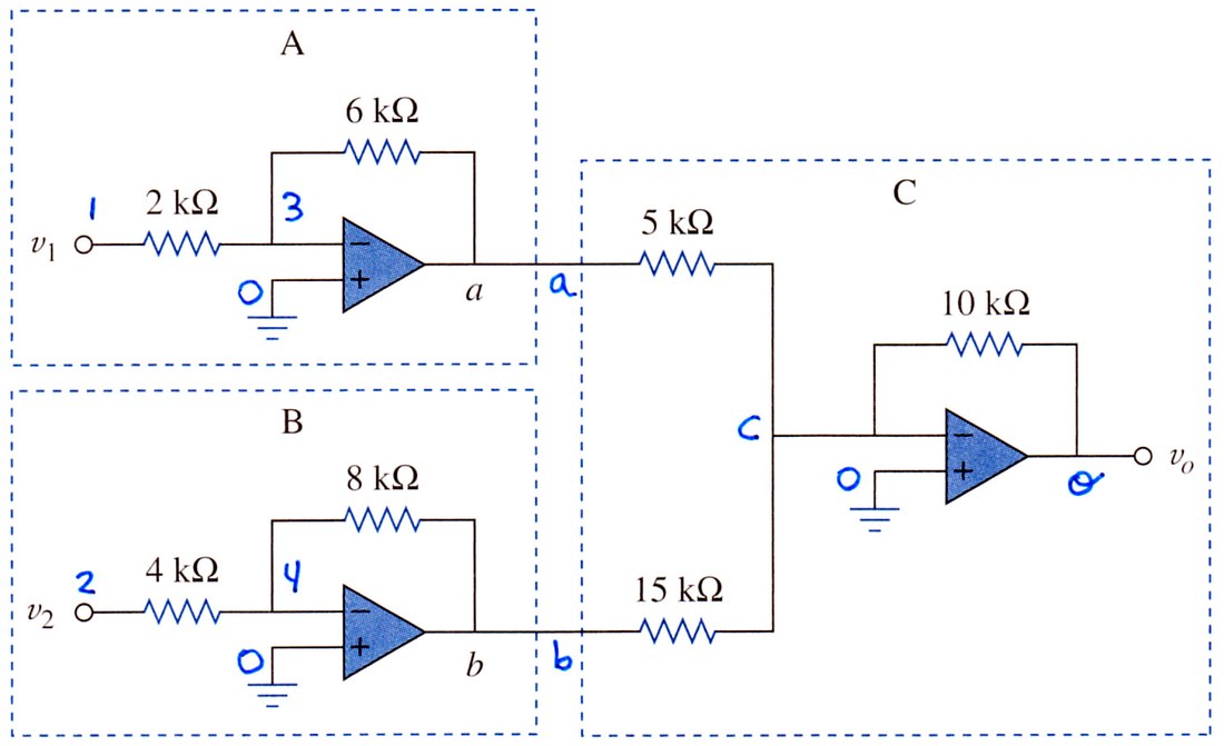
s\dc("e1,1,0,1:e2,2,0,2:r2,1,3,2'k:r4,2,4,4'k:r6,3,a,6'k:r8,4,b,8'k:r5,a,c,5'k:r15,b,c,15'k:r10,c,o,10'k:oa,0,3,a:ob,0,4,b:oc,0,c,o"):approx(vo)The answer, 8.667, is correct.
TR5's Example 4-17 (Cascade)
Derive an expression for vo in terms of the inputs v1 and v2.
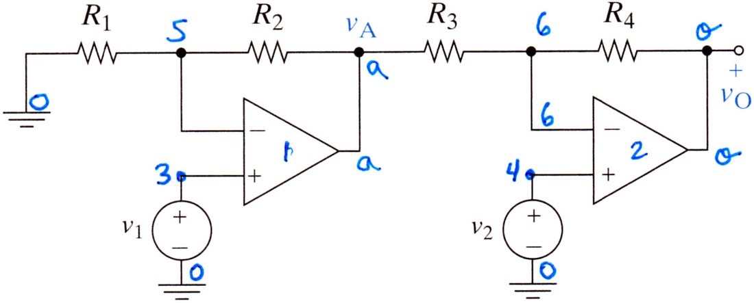
s\dc("r1,5,0,r1:r2,5,a,r2:r3,a,6,r3:r4,6,o,r4:e1,3,0,v1:
e2,4,0,v2:o1,3,5,a:o2,4,6,o"):vo
We get the right answer. Let's compare it with the book's answer.

Our answer, expanded via expand(vo), is shown below:
Playing with it by hand we get a form that, in my opinion, is prettier ;-) than the book's:
TR5's Example 4-18 (Multiple)
Derive an expression for vo in terms of the inputs v1 and v2.

s\dc("e2,a,0,v2:e1,f,0,v1:o2,a,c,b:o1,f,d,e:r1,b,c,r1:r2,c,d,r2:r3,d,e,r3")To find vo, we ask for vb-ve. We get an expression that can easily be rearranged to look like this:
This is exactly the answer from the book:

If you are ever in doubt whether two expressions are the same, enter them both separately into the calculator and compare them with the equality sign. If the answer is 'true', they are the same.