Lesson 1
Direct current analysis
Learn to describe a circuit in Symbulator, and how to run a direct current analysis using dc. Learn how to describe a voltage source using e, and a resistor using r.
Last updated 2026-09-05
I firmly believe one learns best by doing, so I have written this documentation as a tutorial, where you learn Symbulator by working through a series of progressively more diverse and complex examples. In a moment, I'll teach you how to swim. But for now, let me throw you in the deep end!
1.1Run a direct current analysis
I want you to make MAIN the current folder in your calculator, delete all variables you don't need (ideally, the current folder should be empty), and type this:
s\dc("e1,1,0,36:r1,1,2,1'k:r2,2,3,3'k:r3,3,0,2'k")Now I want you to press ENTER.
If you typed everything correctly and your calculator is properly set up with Symbulator, you should have seen BUSY appear in the bottom right corner, and your calculator seemingly go into a trance and spew out a series of cryptic messages. Then, after a few seconds, it should have returned to normal, displaying a short Done.
Congratulations! You have just run your first simulation in Symbulator.
How does it work
Let's now go over what we just did, one piece at a time.
To analyse a direct current circuit in Symbulator, we use a program called s\dc(). The program itself is called dc, but since it is found in the Symbulator folder s, we have to refer to it as s\dc, so the calculator knows exactly what we want. And because it is a program, it carries the parenthesis () after its name.
The dc program takes one argument as its input: the description of the circuit you want to analyse. That input goes inside the parenthesis.
In Symbulator, a circuit description takes the form of a string of text, describing a series of elements, separated by colons.
The circuit description can be passed to the program directly as an argument, as we did above, or it can be stored into a variable whose name is then fed in, like this:
"e1,1,0,36:r1,1,2,1'k:r2,2,3,3'k:r3,3,0,2'k"→cir
s\dc(cir)
The results are exactly the same as doing it in a single step. I like to use cir as the name of the variable where I store my circuits, and that is what you will see in this tutorial, though any valid variable name will do. You will see both ways used throughout.
Look at the elements
Now let's examine the contents of the circuit description. Study it and you will see three colons. In Symbulator, colons separate elements in a circuit description, so putting them aside, this description has four elements:
- The first one is
e1,1,0,36 - the second one is
r1,1,2,1'k - the third one is
r2,2,3,3'k - the fourth one is
r3,3,0,2'k
At the moment they may look cryptic. But by the end of this lesson you will read them with ease.
1.2How to describe a resistor
Notice that the second, third and fourth elements in the list all start with the letter r. These are resistors.
How to name resistors
Every resistor must have a name. As long as it starts with the letter r and is unique, it can be whatever you want. Unique means no other element or node has the same name.
With one exception: rc is reserved in the TI-89 calculator, and cannot name a resistor or anything else.
How to name nodes
Naming the nodes is the first thing we do to solve a circuit. Every node must have a name, and node names must be unique: no other node or element may have the same one. Otherwise they can be whatever you want, with two constraints. The first one is that: at least one node should be called 0 (zero). This will be considered the ground node of your circuit and will have, by definition, a voltage of 0 volts.
The second restriction is that you cannot use the calculator's reserved variables as names. Besides rc, there are c1, c2, c3 … c99, and more exotic ones listed in the calculator's User's Manual.
Values can use SI prefixes
The values of circuit elements are often given with prefixes of the International System (SI) — kilo, milli, micro. So Symbulator has a shorthand for them: an SI prefix in an element's value, preceded by an apostrophe, multiplies it by the corresponding factor, exactly.
For example, an 8 kΩ resistor can be entered in many ways: 8000, 8'k, 8000. and 8E3 are all equivalent, except that the first two are treated as exact and the other two as approximate.
1.3What answers do you get
After the simulation in DC is complete, Symbulator stores a series of answers in the calculator's memory, labelled with easy to remember names for your convenience.
Answer for each node
Symbulator calculates for each node a voltage with reference to ground, which is stored in a variable called v plus the name of the node. For example, for a node called 1, its voltage is stored in a variable called v1.
Answers for each resistor
Symbulator calculates for each resistor the following answers:
- The voltage drop in the resistor, defined as the voltage in the first node minus the voltage in the second node, in volts. For a resistor called r5, this is stored in
vr5. - The current through the resistor, flowing from the first node towards the second, in amperes. For a resistor called rx, this is stored in
irx. - The power consumed by the resistor, in watts. For a resistor called r12, this is stored in
pr12.
By now you should understand the description of the second, third and fourth elements in our example.
1.4How to describe a voltage source
The first element in our example, on the other hand, started with the letter e. This element is a voltage source.
How to name voltage sources
Every voltage source in your circuit must have a unique name that starts with the letter e, and it can be whatever you want.
Values can use SI prefixes
A voltage source's value can use SI prefixes too — they work in the values of every element.
Answers for a voltage source
For each voltage source, the following answers are calculated:
- The voltage drop in the source, defined as the voltage in the first node minus the voltage in the second, in volts. For a source called e5,
ve5. - The current through the source, flowing from the first node towards the second, in amperes. For a source called ex,
iex. - The power consumed — attention: not delivered, but consumed — by the source, in watts. For a source called e12,
pe12. If we want the power delivered, we ask for the negative of this value. - The equivalent resistance of the rest of the circuit, as seen by the source. For a source called e2,
re2.
1.5A numerical DC simulation, step by step
Let's go back now to the simulation we ran earlier. That simulation corresponds to the circuit given in Example 5.7 in Boylestad's Introductory Circuit Analysis (11ed). Moving forward, I will refer to that textbook as B11.
The problem statement and the circuit schematic are reproduced exactly as they appear in the textbook, as they will be for every other problem in this tutorial. Since this is for educational purposes, it is my understanding that it falls squarely within the "fair use" doctrine of copyright law. In any event, no copyright infringement is meant.
B11's Example 5.7

B11's Example 5.7
Solution
All the values in this circuit are numbers: no element value is unknown. This is a numerical circuit — one where we know the numerical value of every element in it.
I will now walk you step by step through the solution. This process applies to most numerical simulations in Symbulator: (1) describe the circuit, (2) run the simulation, and (3) get the answers.
Step 1: Describe the circuit
Description starts with naming the nodes. As we said, you can call them anything you want, number or letter, as long as the name is unique — but one node must always be called 0 (zero), the ground node, with a voltage of 0 V. In this circuit the ground node is marked with the ground symbol. That is not always so; when it is not marked, you pick a node to serve as zero.
I labelled the nodes in this circuit, starting in the ground and moving clockwise, as 0, 1, 2 and 3. It helps me to pencil the names in the schematic itself.

B11's Example 5.7, with the node names pencilled in
After naming the nodes, I am ready to describe the elements of the circuit in Symbulator notation.
Let's start with the source: when I only have one voltage source, like here, I enjoy naming it with a single letter: e. So the voltage source is e,1,0,36: its name is e, its positive node is 1, its negative node is 0, and its value is 36 volts between them.
Now the resistors. I named the first r1 and described it r1,1,2,1'k: its name is r1, its first node 1, its second node 2, and its value 1 kΩ. The second is r2,2,3,3'k, and the third r3,3,0,2'k.
We pass the description to Symbulator as a string: open with a quotation mark, enter each element's description separated by colons, and close with a quotation mark. We can store the string in a variable:
"e,1,0,36:r1,1,2,1'k:r2,2,3,3'k:r3,3,0,2'k"→cirStep 2: Run the simulation
We can now ask Symbulator to simulate this circuit in direct current:
s\dc(cir)Symbulator says Done when a simulation completes. It took my calculator 16 seconds to solve this circuit, in which time it found 16 answers and stored each in a memorably named variable in the current folder.
For a DC analysis, these answers are as follows:
- The voltage of each node, so the voltages of nodes 1, 2 and 3 are in v1, v2 and v3.
- The current through each element. The direction of the current is defined as going from the first node in the element's description to the second.
- The voltage drop in each element, defined as the difference in voltage between the first node in the element's description and the second, in that order.
- The power consumed in each element. An important point is that this is the power consumed, not the power delivered.
- Finally, for each source, the equivalent resistance of the rest of the circuit as seen by that source.
Step 3: Get the answers
We can now answer the six questions in the problem.
Answer to question (a). The equivalent resistance as seen by the source e:
re6000That is 6 kΩ. Correct.
Answer to question (b). Current Is is defined in the schematic as the current flowing through the source, in the direction that goes from node 0 to node 1. One way to find this value is evaluating the negative of the current through the source, which as you know flows in the opposite direction:
–ie.006That is 6 mA. Another way, since this is a series circuit where every element carries the same current, is to evaluate the current through any of the resistors.
Answer to question (c). The voltage drop in resistor R1 — since its polarity is defined in the schematic in the same way it is defined in our circuit description — is as follows.
It is found by evaluating vr1: the calculator returns 6, that is 6 V. For R2, vr2 gives 18 V. And for R3, vr3 gives 12 V. These are all the right answers.
Answer to question (d). Since the problem asks for the power supplied by the source, and we know that pe has the power consumed by it, we need to evaluate the negative of it, and we get .216, that is 216 mW delivered.
Answer to question (e). The power consumed by the resistors is found evaluating pr1, pr2 and pr3. We get .036, .108 and .072, that is 36 mW, 108 mW and 72 mW consumed, respectively.
Answer to question (f). Let's ask the calculator whether the sum of the consumed power in the resistors equals the power supplied by the source:
pr1+pr2+pr3=–petrueThis is the right answer, and concludes the solution to this, your first ever problem in Symbulator.
1.6Instructive numerical examples, solved
Numerical problems in DC using e and r
These practice problems are taken from several textbooks, chosen because they apply only the concepts you have learned so far. They let you practise and reinforce them before Lesson 2.
The problem below comes from Figure 1-26 (a) in Hyatt and Kemmerly's Engineering Circuit Analysis (5ed). Moving forward, we will refer to that textbook as HK5.
HK5's Figure 1-26
We are asked for the current, voltage drop and power consumed in each resistor, the power delivered by each voltage source, and a check that the powers in the circuit add up to zero.
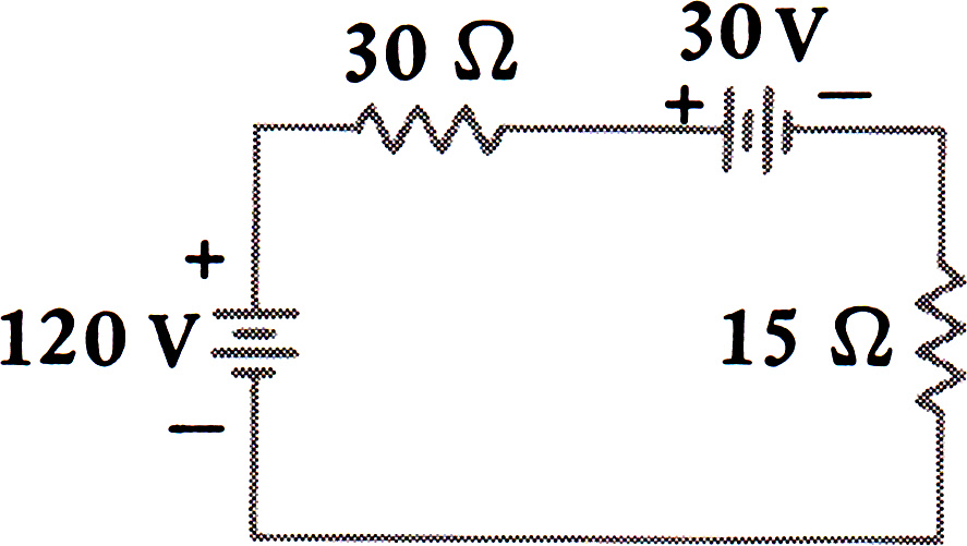
Here is my solution.
I named the nodes thus: the bottom node 0, and the top nodes, from left to right, 1, 2 and 3. My description of the circuit, as the argument of the DC simulation command:
s\dc("e1,1,0,120:r1,1,2,30:e2,2,3,30:r2,3,0,15")When the simulation is done, you can ask the calculator for the answers you need:
- Evaluating
ir1orir2gets the current in the resistors: 2 A - Evaluating
vr1gets the voltage drop in the 30Ω resistor: 60 V - Evaluating
vr2gets the voltage drop in the 15Ω resistor: 30 V - Evaluating
pr1gets the power consumed in the 30Ω resistor: 120 W - Evaluating
pr2gets the power consumed in the 15Ω resistor: 60 W - Evaluating
-pe1gets the power delivered by the 120V source: 240 W - Evaluating
-pe2gets the power delivered by the 30V source: -60 W. The source consumes 60W, so it delivers negative 60W. - Evaluating
pr1+pr2+pe1+pe2gets the sum of powers: 0 W. As expected.
Wasn't that easy?
We could also have asked for all the answers with one array:
{ir1,vr1,vr2,pr1,pr2,-pe1,-pe2,pr1+pr2+pe1+pe2}B11's Example 5.20
The practice problems get progressively more complicated, so you build up your 'symbulating' skills with confidence.

I named the nodes clockwise from the ground: 0, 1, 2, 3 and 4. My circuit description, as an argument of the DC simulation command:
s\dc("e1,1,0,50:r1,1,2,4:e2,2,3,12.5:r2,3,4,7:r3,4,0,4")When it's done, ask for the answers we need. Evaluating ir1 gets the current I: 2.5 A. Evaluating vr2 gets the voltage drop in the 7Ω resistor: 17.5 V
B11's Example 6.13

Since the ground is the bottom node, I named it 0. I named the top node 1.
s\dc("e,1,0,24:r1,1,0,10:r2,1,0,220:r3,1,0,1.2'k")- Evaluating
regets the total resistance: 9.49 Ω - Evaluating
-iegets us the source current: 2.53 A - Evaluating
ir1gets I1: 2.4 A,ir2gets I2: 109 mA, andir3gets I3: 20 mA.
B11's Example 7.2
Determine I4, IS and V2.
My solution: I named the top node 1, and the other 2:
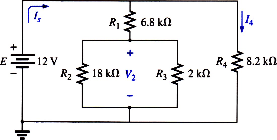
s\dc("e,1,0,12:r1,1,2,6.8'k:r2,2,0,18'k:r3,2,0,2'k:r4,1,0,8.2'k")Answers: v2 is 2.51 V, -ie (i.e. IS) is 2.86 mA and ir4 is 1.46 mA.
B11's Example 7.7
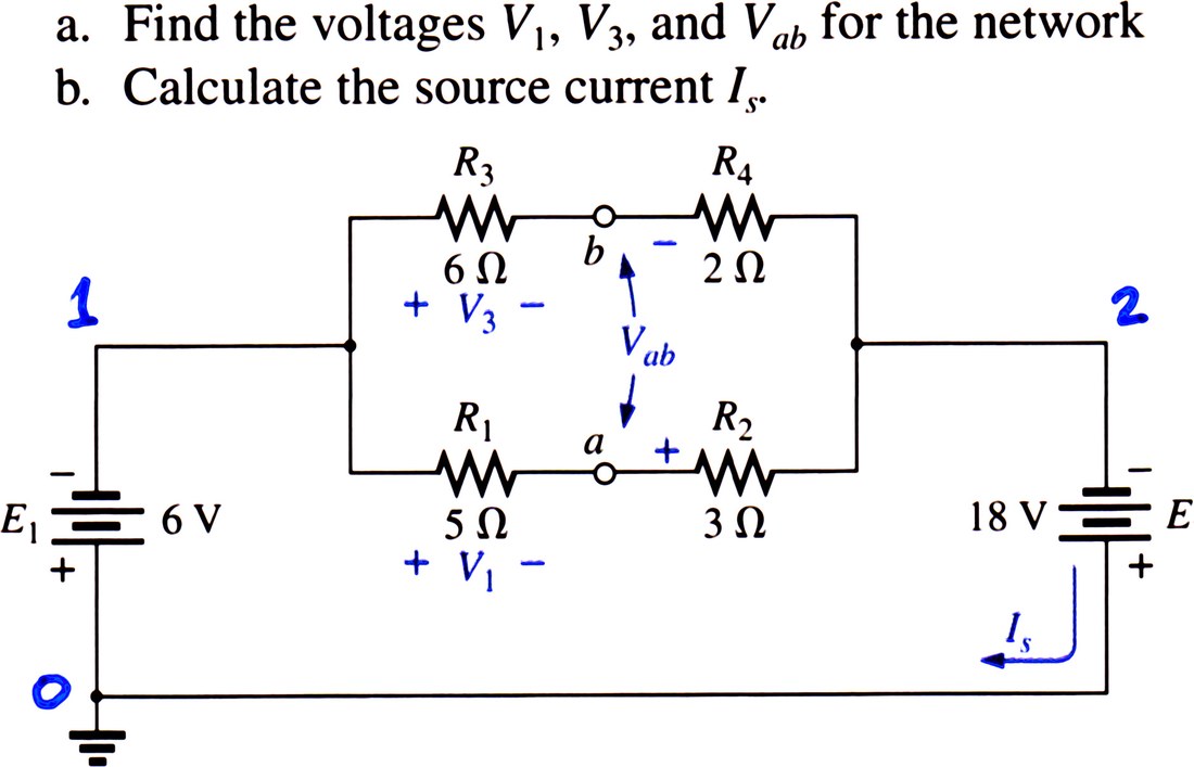
I have labelled the node names I used. My solution:
s\dc("e1,0,1,6:e2,0,2,18:r1,1,a,5:r2,a,2,3:r3,1,b,6:r4,b,2,2")Answers: vr1 is 7.5 V, vr3 is 9 V. For Vba, vb-va is -1.5 V. For IS, -ie2 is 3 A.
B11's Figure 7.32
Determine I6 and V6.

My solution:
s\dc("e,1,0,240:r1,1,2,5:r2,2,0,6:r3,2,3,4:r4,3,0,6:r5,3,4,1:r6,4,0,2")Answers: ir6 is 10 A, and vr6 is 20 V.
B11's Example 7.10
Calculate the indicated currents and voltages.

My solution:
s\dc("r2,2,3,8'k:r1,3,4,4'k:r3,1,2,12'k:r4,1,4,24'k:
r5,1,0,12'k:e,4,0,72:r6,4,5,12'k:r7,5,0,9'k:r8,5,6,3'k:r9,0,6,6'k")
Answers: ir5 is 3 mA, -ie (i.e. IS) is 7.36 mA, and vr7 is 19.6 V.
B11's Example 7.4
Determine the currents I1, I2, IA, IB and IC, and the voltage drop in areas A, B and C.

My solution:
s\dc("e,1,0,16.8:r1,1,2,9:r2,1,2,6:r3,2,3,4:r4,3,0,6:r5,3,0,3:r6,2,0,3")Current I1 is found via ir1 = 1.2 A, I2 via ir2 = 1.8 A, IA, via -ie = 3 A, IB via ir3 = 1 A and IC via ir6 = 2 A. The voltage drop in area A is vr1 = 10.8 V; in both B and C it is v2 = 6 V.
B11's Example 6.15

My solution:
s\dc("e,1,0,28:r1,1,0,1.6'k:r2,1,0,20'k:r3,1,0,56'k")- Evaluating
regets the total resistance: 1.44 kΩ - Evaluating
ir1gets 17.5 mA,ir2gets 1.4 mA, andir3gets 0.5 mA - Evaluating
-pegets the power: 543 mW
These are the correct answers.
B11's Figure 7.40
Determine Vb and Vc.
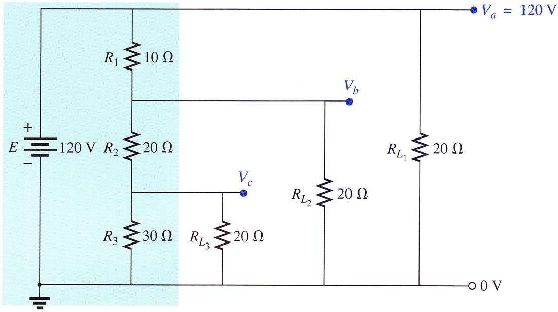
My solution:
s\dc("e,a,0,120:r1,a,b,10:r2,b,c,20:r3,c,0,30:
rl1,a,0,20:rl2,b,0,20:rl3,c,0,20")
Answers: vb is 66.21 V, and vc is 24.83 V.
B11's Example 8.10
Determine the current through each resistor.
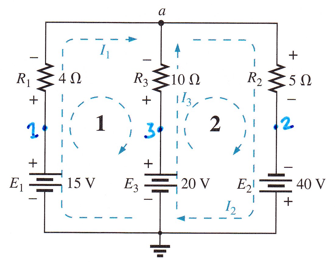
My solution:
s\dc("e1,1,0,15:r1,1,a,4:e3,3,0,20:r3,3,a,10:e2,0,2,40:r2,a,2,5")Through an array, and using the approx command, we ask for all the three answers:
approx({ir1,ir2,ir3})The calculator returns {4.77,7.18,2.41} meaning IR1 =4.77A, IR2 =7.18A and IR3 =2.41A. These are the correct answers. We could get this answer in a single-line command:
s\dc("e1,1,0,15:r1,1,a,4:e3,3,0,20:r3,3,a,10:e2,0,2,40:r2,a,2,5"):
approx({ir1,ir2,ir3})
Moving forward, we will often use this single-line approach for getting our answers.
B11's Example 7.6
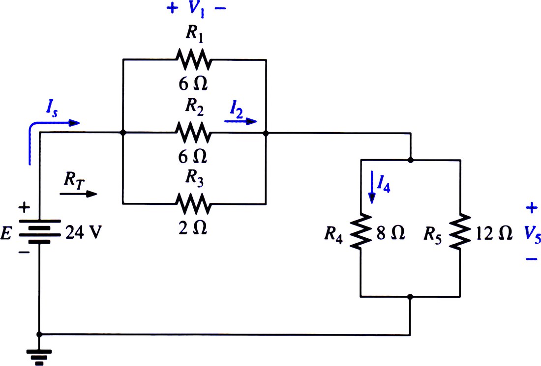
My solution:
s\dc("e,1,0,24:r1,1,2,6:r2,1,2,6:r3,1,2,2:r4,2,0,8:r5,2,0,12")Answer: -ie is IS=4 A, ir2 is I2 = .8 A, ir4 is I4=2.4 A, vr1 is V1=4.8 V, vr5 is V5=19.2 V.
B11's Example 7.11
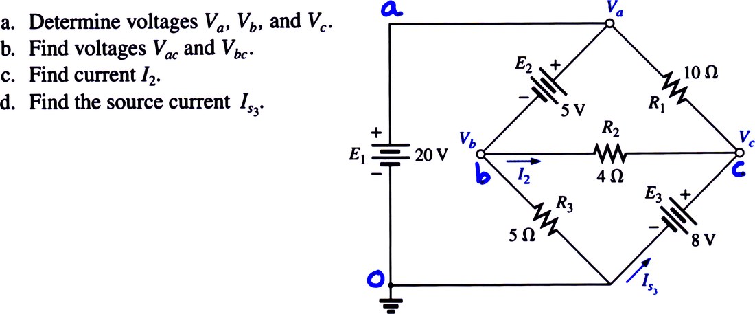
My solution:
s\dc("e1,a,0,20:e2,a,b,5:e3,c,0,8:r1,a,c,10:r2,b,c,4:r3,b,0,5")Answers: va=20 V, vb=15 V, vc=8 V, va-vc= 12 V, vb-vc=7 V, ir2=1.75 A, IS via -ie3=-2.95 A
B11's Example 8.24
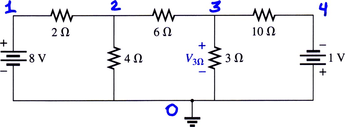
Find the voltage drop in the 3Ω resistor.
My solution:
s\dc("e8,1,0,8:r2,1,2,2:r4,2,0,4:r6,2,3,6:r3,3,0,3:r10,3,4,10:e1,0,4,1")Now, evaluating vr3 via approx(vr3) finds that V3Ω is 1.1 V. This is correct.
B11's Example 8.18
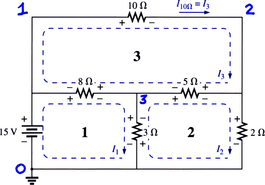
Find the current through the 10Ω resistor in the network shown.
My solution:
s\dc("e15,1,0,15:r10,1,2,10:r8,1,3,8:r5,3,2,5:r3,3,0,3:r2,2,0,2"):
approx(ir10)
We find that ir10 = 1.22 A.
B11's Example 8.26
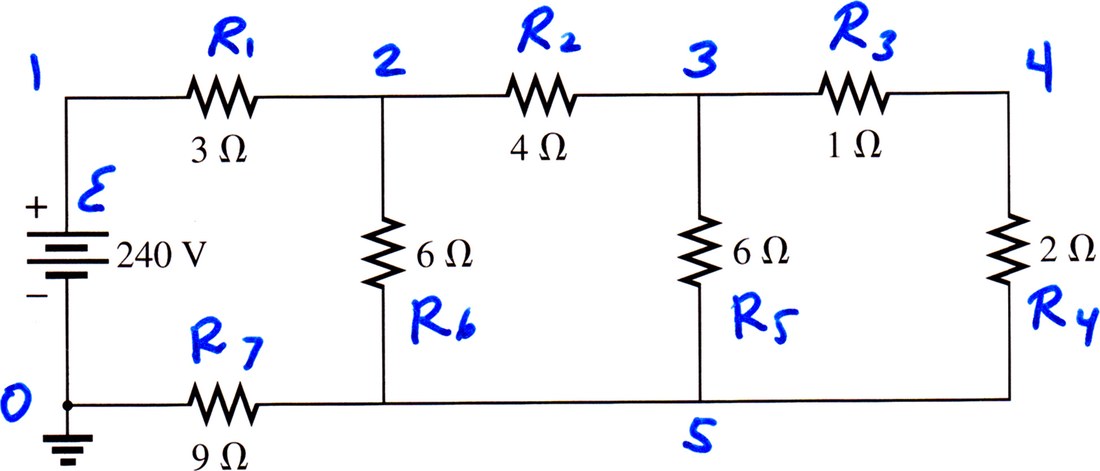
Find the voltage drop in the 2Ω resistor.
My solution is below:
s\dc("e,1,0,240:r1,1,2,3:r2,2,3,4:r3,3,4,1:
r4,4,5,2:r5,3,5,6:r6,2,5,6:r7,5,0,9")
Evaluating approx(vr4), we find the voltage drop in R4 (the 2Ω resistor): it is 10.67 V
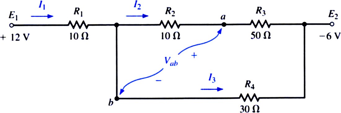
Circuits with ‘hidden source'
Sometimes the schematics of circuits are presented in such a way that sources of voltage are not shown explicitly, yet their voltage is provided. These are what I call ‘hidden source' problems. Below I offer two examples of these types of problems. Both are taken from the textbook Circuit Analysis: Theory and Practice (3ed) by Allan H. Robbins and Wilhelm C. Miller, to which from this point on we will refer as RM3.