
Lesson 7
Alternating current analysis
Learn how to run an alternating current analysis (via phasor analysis) using ac. Learn how to describe capacitors, inductors, impedances and admittances, and sources for AC analysis.
Last updated 2023-07-08
In this lesson you will learn how to use the ac program to solve AC circuits in Symbulator. You will also learn how to describe the elements you already know so they suit AC analysis, and how to use er and th in their AC mode.
7.1AC analysis in Symbulator
The main thing to know is that in AC mode Symbulator understands phasors — complex numbers. It uses them in the input, in the analysis and in the output.
The ac program
Symbulator has a program for analysing AC circuits, called s\ac. Unlike s\dc and s\tr, which take only the circuit description, s\ac takes two inputs: the description, in a string, and the frequency of the circuit in radians per second.
The AC mode
Besides s\ac itself, you can use s\er, s\th and s\ex in their AC mode: select AC when asked what type of analysis you want. This lesson has examples of all of them.
Describing elements for AC
When describing a circuit for AC analysis, element values have to be written the way this analysis expects. Valueless elements, like the short circuit and the op amp, are unchanged. Here's how to describe the ones with values:
- Current sources j and voltage sources e accept complex values. You can declare their value in rectangular form, e.g.
10-3𝐢, or in angular form, e.g.(100∠120°). - The element r no longer represents just a resistor: it now represents an impedance. If you are wondering why we didn't use the letter z, wait until we get to two-ports. In AC analysis, r accepts complex numbers as its value, such as
10-3𝐢. We use r to describe resistors (real values) and conductances (real values, inverted), but also impedances (complex values) and admittances (the inverse of their complex value). - The elements c and l are used to describe capacitors and inductors only when their values are given in farads and henries, respectively. For AC analysis their description no longer requires the fifth field for the initial condition, since alternating current analysis focuses on the steady state after transient effects are long gone. So we only use the name, the two nodes, and the value.
The values of all of these elements can use SI prefixes.
What answers do you get
You get the same answers you did in DC, except that now they are phasors. The one difference is that now, besides the real power consumed, you also get the complex power consumed. We will discuss this in Lesson 8.
Rectangular or polar
A phasor can be written two ways, and circuit problems use both: in rectangular form as 3 + 4j, or in polar form as an amplitude and an angle, 5∠53.13°. They are the same number. Which one you want depends on the question — rectangular adds and subtracts easily, polar multiplies and divides easily, and textbook answers are usually quoted in polar.
Symbulator answers in rectangular form, and the aa tool converts one answer at a time. You will see it used throughout this lesson.
7.2Solved numerical examples
With values in F and H
AS7's Example 9.9
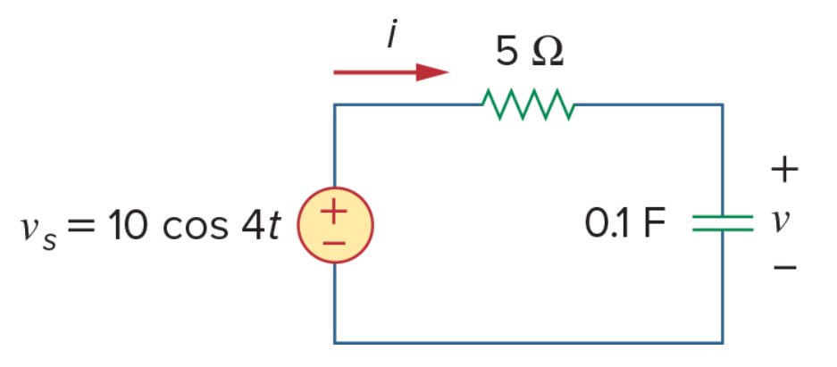
Find v(t) and i(t).
AS7's Example 9.9
Solution
Since this is the first AC problem we will solve, I will explain every step, including the manual ones, in full detail.
Step 1: sinusoids to phasors. We have to express the value of the source in terms Symbulator can understand, so we convert it from a sinusoid to a phasor: 10∠0°. We can pass this as (10∠0°) or, since the angle is zero, simply as 10.
Step 2: note the frequency. The circuit has a capacitor with a value given in farads. Because of this, Symbulator will need the frequency, given by the problem as 4 rad/s, to convert that value into an impedance in ohms.
Step 3: describe the circuit.
"e,1,0,10:r1,1,2,5:c,2,0,.1"→cir
s\ac(cir,4)
Notice that, in our circuit description, the order we give to the nodes of the resistor and the capacitor is chosen to be convenient for the answers we will ask for.
Step 4: read the answers. Once Symbulator is done, you should take a look at what it found:
- the usual voltages in the nodes, voltage drops in the elements, and currents through the elements, in variables that should be familiar by now
- the average power consumed in the source and the resistor, in
apeandapr1. None is given for the capacitor, since capacitors and inductors do not consume real power. - the complex power consumed in all elements, in
sc,seandsr1 - the equivalent impedance of the rest of the circuit as seen by the source, in
ze
To get the answers we need for this problem in particular, we ask for ir1 and vc. It is likely that the calculator will give you the answers in rectangular form, with a real part and an imaginary part.
If we want to see them as an amplitude and angle, we can use Symbulator's aa tool:
s\aa(ir1)1.789∠26.57°This is correct. You manually convert it to a sinusoid, by putting it back in the same terms the input was given in:
Asking for the capacitor voltage the same way gives 4.472∠-63.43°, that is,
which is correct.
Future solved problems will not include this level of detail in the solution, only the circuit description and the commands we give.
AS7's Practice Problem 9.9
Determine v(t) and i(t).

AS7's Practice Problem 9.9
Solution
"e,1,0,(20∠30°):r1,1,2,4:l,2,0,.2"→cir
s\ac(cir,10)
We ask for the current in the resistor and get 4.472∠3.43°, and for the voltage in the inductor and get 8.944∠93.43°. Both are correct.
AS7's Example 9.10
Find the input impedance of the circuit. Assume that the circuit operates at ω = 50 rad/s.

AS7's Example 9.10
Solution
Since this is a passive circuit, to reduce it we will use the er tool.
"ca,1,2,2'm:r1,2,3,3:cb,3,0,10'm:l1,2,4,.2:r2,4,0,8"→cir
s\er(cir,1,0)
When asked what type of analysis, choose AC. Since there are capacitors in farads and an inductor in henries, Symbulator will ask you for the frequency; enter 50. Once the program is done, ask for the equivalent impedance, zeq.
3.22–𝐢11.07That is 3.22 − j11.07 Ω, which is correct.
AS7's Problem 9.35
Find the steady-state current i in the circuit when vs(t) = 50 cos 200t V.

AS7's Problem 9.35
Solution
The capacitor is in farads and the inductor in henries, so Symbulator needs the frequency, and the source is entered as its phasor: 50 cos 200t is 50 at an angular frequency of 200.
"e,1,0,50:r,1,2,10:c,2,3,5'm:l,3,0,20'm"→cir
s\ac(cir,200)
Choose AC. Symbulator asks for the frequency because of the farads and henries; enter 200. Then ask for s\aa(ir).
s\aa(ir)We get 4.789∠-16.7° A.
That is 4.789 A at an angle of −16.7°, which is correct.
With values in Ω only
When the values of all the capacitors and inductors in the circuit are given in imaginary ohms, they must be entered in the circuit description as impedances, r. In these cases, Symbulator will not need a frequency.
AS7's Problem 9.37
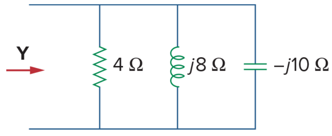
Determine the admittance Y for the circuit.
AS7's Problem 9.37
Solution
Since the values are in ohms, these are all impedances. This is a passive circuit, so we could use the er tool. However, the structure of this circuit is so simple that we can reduce it by hand. The problem asks for the equivalent admittance, so our answer will be the inverse of the equivalent impedance:
1/(s\pr({4,𝐢8,-𝐢10}))0.25-0.025𝐢That is 0.25 − j0.025 S, which is correct.
AS7's Problem 9.39
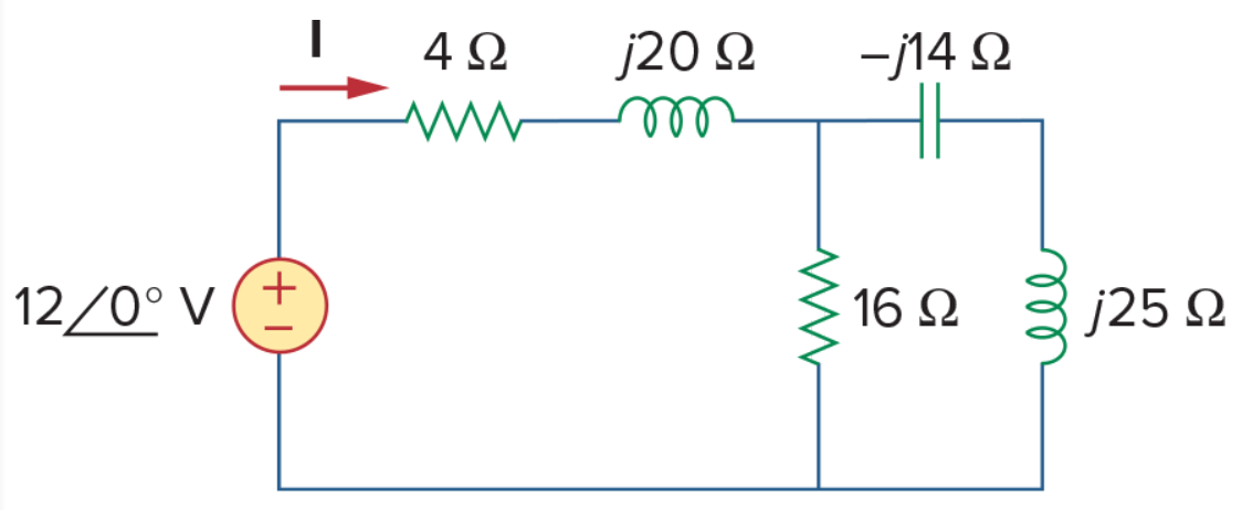
For the circuit shown, find the equivalent impedance, and use that to find the current I. Let omega = 10 rad/s.
AS7's Problem 9.39
Solution
The frequency the question gives is superfluous: every value is already in ohms. Nothing here needs a full simulation either; the equivalent impedance is one expression, using the parallel shorthand:
4+𝐢20+s\pr({16,-𝐢14+𝐢25})→zeq9.135+𝐢27.47That is 9.135 + j27.47 Ω. The current is the source voltage divided by it:
s\aa(12/zeq)We get 414.5∠-71.6° mA.
That is 414.5 mA at an angle of −71.6°, which is correct.
AS7's Problem 9.73
Determine the equivalent impedance for the circuit.

AS7's Problem 9.73
Solution
Eight impedances and no source: a job for Find equivalent rather than a solve. The names carry the two nodes each element bridges, a convenience only.
"r10,1,0,𝐢6:r20,2,0,𝐢8:r30,3,0,𝐢8:r40,4,0,𝐢12:r12,1,2,2:r23,2,3,-𝐢6:r34,3,4,4:r14,1,4,-𝐢4"→cir
s\er(cir,1,0)0.3794+𝐢1.46That is 0.3794 + j1.46 Ω, which is correct.
With dependent sources
A dependent source is described exactly like an independent one — the value is just an expression naming another element's answer instead of a number.
Version 7 runs the quantity and the element together, as in 2icx.
AS7's Example 10.1
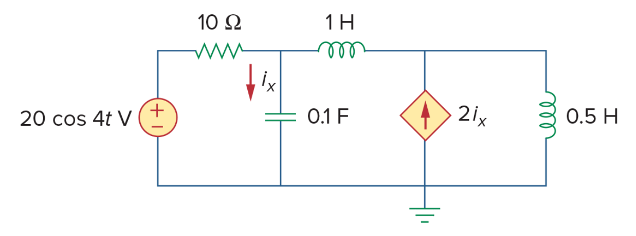
Find ix in the circuit.
AS7's Example 10.1
Solution
The current source is controlled by the current through the capacitor cx, which is what the last field of j1 says.
"e1,1,0,20:r1,1,2,10:cx,2,0,.1:l1,2,3,1:j1,0,3,2icx:l2,3,0,.5"→cir
s\ac(cir,4)s\aa(icx)We get 7.59∠108.4° A.
That is 7.59 A at an angle of 108.4°, which is correct.
AS7's Practice Problem 10.1
Find v1 and v2 in the circuit.

AS7's Practice Problem 10.1
Solution
This one is controlled by a voltage rather than a current — three times the voltage across rx.
"j,0,1,10:rx,1,0,2:c,1,2,.2:l,2,0,2:r,2,3,4:e,3,0,3vrx"→cir
s\ac(cir,2){s\aa(v1),s\aa(v2)}We get 11.33∠60.02° V and 33.02∠57.13° V.
Both are correct.
AS7's Example 10.13
Obtain vo and io in the circuit.
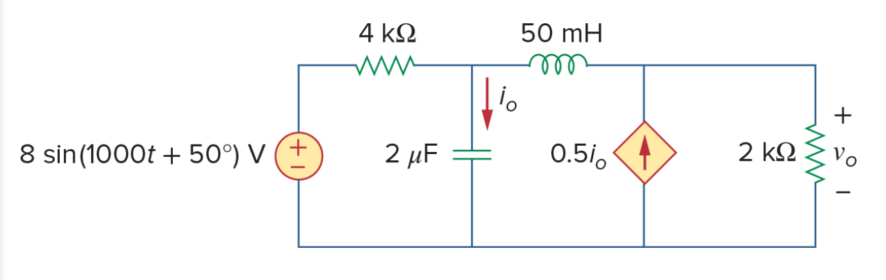
AS7's Example 10.13
Solution
The book wants its answers in terms of cosine rather than sine, so the source is taken as 8 cos(1000t − 40°) — as a phasor, (8∠-40°).
Note the decimal points on the values. They make the arithmetic approximate, which here is what you want: an exact solve of this circuit carries surds through every step for no benefit.
"e1,1,0,(8.∠-40º):r1,1,2,4.'k:co,2,0,2.'µ:l1,2,3,50.'m:j1,0,3,.5ico:ro,3,0,2.'k"→cir
s\ac(cir,1000.){s\aa(vro),s\aa(ico)}We get 1.55∠-95.18° V and 3.26∠-3.74° mA.
That is 1.55 V at −95.18° and 3.26 mA at −3.74°, both correct.
AS7's Example 10.14
Find V1 and V2 in the circuit.
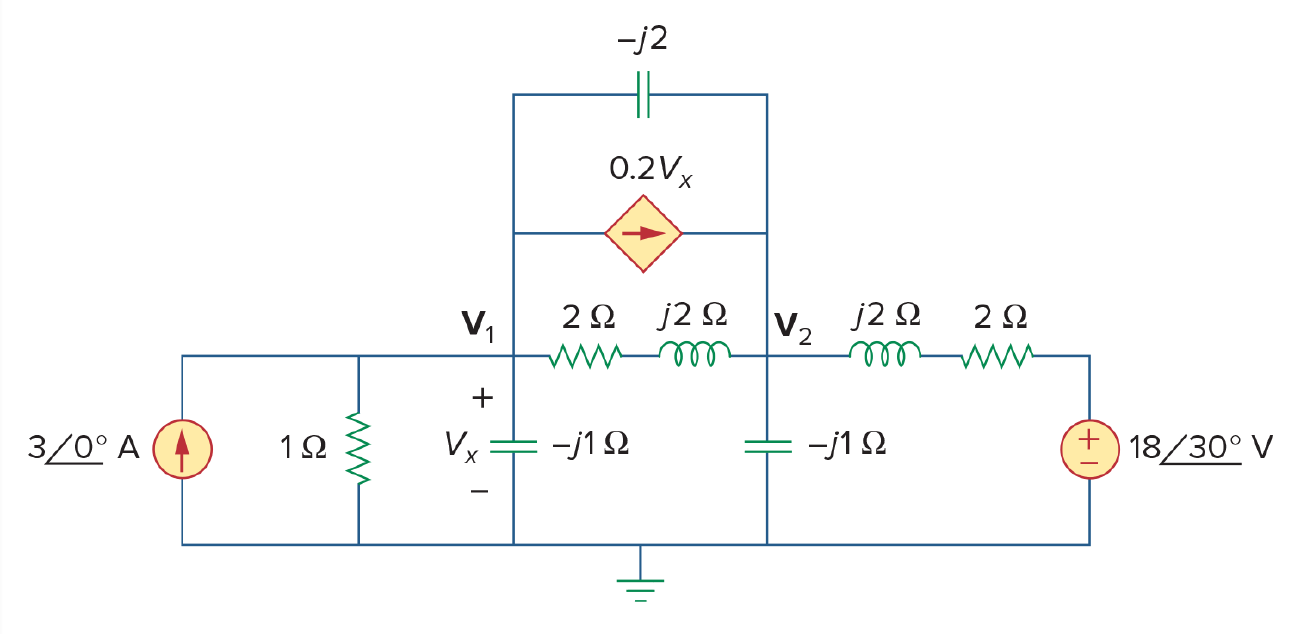
AS7's Example 10.14
Solution
Every value here is already in ohms, so no frequency matters. Again the decimal points keep the arithmetic approximate.
"j1,0,1,3.:r1,1,0,1.:rx,1,0,-𝐢1.:r3,1,2,-𝐢2:j2,1,2,.2vrx:r4,1,2,2.+𝐢2.:r5,2,0,-𝐢1.:r6,2,3,2.+𝐢2.:e1,3,0,(18.∠30º)"→cir
s\ac(cir,ω){s\aa(v1),s\aa(v2)}We get 2.708∠-56.73° V and 6.914∠-80.70° V.
That is 2.708 V at −56.73° and 6.914 V at −80.70°, both correct.
7.3Solved numerical-from-symbolic examples
AS7's Problem 9.89
Calculate the value of C so that the net impedance is purely resistive at 2 kHz.

AS7's Problem 9.89
Solution
The answer given by the book is 25 µF. But I think this is one of those unfortunately common instances where there is a mistake in the book. I believe they meant to ask "at 2k rad/s", because that is the frequency at which the answer they give is right. Let me tell you how I solved this problem and I will let you be the judge.
"c,1,0,c:r1,1,2,10:l,2,0,5'm"→cir
s\er(cir,1,0)
When asked, specify AC. Then we are asked for the frequency. The problem gives 2000 Hz; Symbulator asks for radians per second, so I enter 2π2E3. I could also have entered 12566.37.
Notice two things. First, I did not use an SI prefix: the shorthand only works in the circuit description string. Second, I used 2E3 rather than 2000 because I wanted an approximate value — with exact values, cSolve took too long.
Once the simulation finishes, solve for the value of c that makes the imaginary part of the equivalent impedance zero:
solve(imag(zeq)=0,c)The answer is c = 0.000001235, or 1.235 µF. This is not the answer the book gives.
I first used cSolve here, which also works, but my friend Qifan Wang — who verified my answers — pointed out, correctly, that it is not necessary: focusing on the imaginary part removes every reference to the complex operator, so we are solving an equation in real terms only.
Let's now repeat the process, using what I suspect is the frequency they meant: 2000 rad/s. I also want to show you something cool. Now that we know the answer is in the range of µF, we can declare the value of the capacitor as c'µ, so that the value of c we get will be in that scale:
"c,1,0,c'µ:r1,1,2,10:l,2,0,5'm"→cir
s\er(cir,1,0)
solve(imag(zeq)=0,c)
The answer is c = 25, that is to say 25 µF. This is the right answer in the book. So they asked the wrong question — they asked it using the wrong frequency unit.
7.4Solved symbolic examples
AS7's Problem 10.69
Find Vo/Vs.
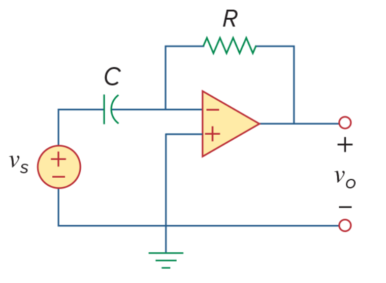
AS7's Problem 10.69
Solution
"e,1,0,vs:c,1,2,c:r1,2,o,r:o,0,2,o"→cir
s\ac(cir,ω)
We ask for vo/vs and get −c·ω·r·𝐢, which is correct.