Examples from Alexander & Sadiku 7e
Fifty-two worked examples from Fundamentals of Electric Circuits, each described in Symbulator and checked against the answer the book prints.
Last updated 2026-09-14
Here is a selection of problems from Fundamentals of Electric Circuits, 7th edition, by Charles K. Alexander and Matthew N. O. Sadiku (McGraw-Hill). The Course's own lessons already draw many of their problems from this book, and none of the fifty-two here repeats one of theirs. These are not the easiest problems in the book, but they are well suited to showing what Symbulator can do, since they are the ones where the distance between describing a circuit and solving it by hand is widest. The book works each of them by a named method, and here each question is trimmed to what is asked, since Symbulator is told the circuit and never the method.
The problems and diagrams are reproduced for the purpose of teaching students how to use Symbulator, under the principle of fair use. No copyright infringement is intended.
How to read an entry
Each entry gives the book's question, the book's own figure, the Symbulator description, the analysis to choose, and the answers. Every value on the page, in a panel or in a sentence, was compared with the answer the book prints, and they agree. Where the two are written differently, the entry's paragraph says so.
The names are the app's own. i_r3 is the current through the element called r3, v_2 the voltage at node 2, p_e the power consumed by the source called e, and v_r6 the voltage across r6. The book names its quantities differently, so each entry says which of the app's answers is which of the book's.
Every circuit is in the app already
Nothing here has to be typed. All fifty-two circuits ship with Symbulator as a built-in example book. Open Built-in Examples and pick Alexander & Sadiku 7ed from the list of books. The entries are named for the example each one comes from, and each arrives with its note, its picture, its settings, its Solve card fields and the analysis it wants already set.
Pick one, press Run Symbulator, and the answers below are what you get. Working with input files explains what an entry remembers and how to save your own.
Direct current — DC
Twenty-one resistive problems open the chapter. The book's method, whether node voltages, mesh currents or a Thévenin equivalent, is a way of getting an answer by hand, not a property of the answer. Symbulator is told the circuit and never told the method, so the same kind of description serves whichever chapter a problem came from. Where the book asks for mesh currents, which belong to no single element, the By-Hand Equations card names them. Seven of these problems are answered by the Find equivalent card, three are op-amp circuits, and the last five are two-ports from the book's final chapter, each written as an element of its own.
AS7's Example 2.15
Open in app ↗Open in split view
Obtain (a) the equivalent resistance \(R_{ab}\) for the circuit in the figure and (b) use it to find current \(i\).

Alexander & Sadiku, 7th edition — the circuit for Example 2.15
Solution
The circuit consists of a 120 V source feeding a network of six resistors between terminals a and b. The network is neither a series nor a parallel combination: its 5 Ω resistor bridges the two middle nodes. The question wants the resistance the source sees, \(R_{ab}\), and the current \(i\) it delivers. We describe the network as it is drawn, keeping the figure's letters a, c and n and taking terminal b as ground, node 0. We name the resistors r1 to r6 in the order 12.5 Ω, 15 Ω, 10 Ω, 20 Ω, 5 Ω and 30 Ω.
e,a,0,120
r1,a,c,12.5
r2,c,0,15
r3,a,n,10
r4,n,0,20
r5,c,n,5
r6,a,0,30
Set Analysis to DC — direct current. Set Rounding in Settings to approx to n digits with n = 4.
The source's card reports the resistance the source sees, r_e, which is \(R_{ab}\). It also reports the source's current into its positive terminal, so the current \(i\) the source delivers is the opposite of ie.
Symbulator returns (a) r_e = 9.632 Ω (the book's \(R_{ab}\)) and i_e = -12.46 A.
(b) So \(i\) = 12.46 A, the opposite of ie.
AS7's Example 3.4
Open in app ↗Open in split view
Find the node voltages in the circuit of the figure.
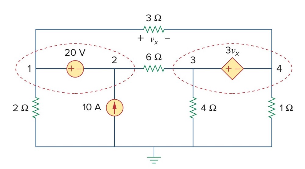
Alexander & Sadiku, 7th edition — the circuit for Example 3.4
Solution
The circuit consists of an independent voltage source, a dependent one, a current source and five resistors, and the question wants the voltage at each of its four nodes. The dependent source is worth three times \(v_x\), the voltage across the 3 Ω resistor. We keep the figure's node numbers, 1 to 4, with the bottom rail as ground, and name the resistors after their values. So \(v_x\) is the voltage drop across r3, and the dependent source's value is 3*vr3. We write each voltage source positive node first, as its polarity marks give, and name the two e1 and e2.
e1,1,2,20
r3,1,4,3
r6,2,3,6
e2,3,4,3*vr3
r2,1,0,2
j,0,2,10
r4,3,0,4
r1,4,0,1
Set Analysis to DC — direct current. Set Rounding in Settings to approx (full precision).
Symbulator returns v_1 = 26.667 V, v_2 = 6.6667 V, v_3 = 173.33 V and v_4 = -46.667 V.
AS7's Practice Problem 3.4
Open in app ↗Open in split view
Find \(v_1\), \(v_2\), and \(v_3\) in the circuit of the figure.
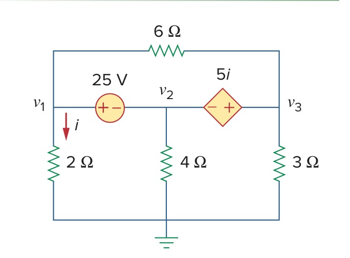
Alexander & Sadiku, 7th edition — the circuit for Practice Problem 3.4
Solution
The circuit consists of an independent voltage source, a dependent one and four resistors, and the question wants the three node voltages. The dependent source is worth five times \(i\), the current down through the 2 Ω resistor. We call the nodes 1, 2 and 3 after the book's \(v_1\), \(v_2\) and \(v_3\), with the bottom rail as ground, and name the resistors after their values. So \(i\) is the current through r2, and the dependent source's value is 5*ir2. Its positive mark is on node 3's side, so we write it e2,3,2,5*ir2.
e1,1,2,25
r6,1,3,6
e2,3,2,5*ir2
r2,1,0,2
r4,2,0,4
r3,3,0,3
Set Analysis to DC — direct current. Set Rounding in Settings to approx (full precision).
Symbulator returns v_1 = 7.6087 V, v_2 = -17.391 V and v_3 = 1.6304 V.
AS7's Example 3.7
Open in app ↗Open in split view
For the circuit in the figure, find \(i_1\) to \(i_4\).

Alexander & Sadiku, 7th edition — the circuit for Example 3.7
Solution
The circuit consists of an independent current source, a dependent one, a 10 V source and five resistors, and the question wants its four mesh currents, \(i_1\) to \(i_4\), one for each loop of the figure, all clockwise. The dependent source is worth three times \(I_o\), the current up through the 10 V source. We name the nodes along the middle of the figure p, x, y and z from left to right, with the bottom rail as ground. A mesh current is the current of any element that only its own mesh contains, so each one can be read off an element's card, as long as the element is written in the direction of the book's arrow. A current is counted from an element's first node to its second. The 2 Ω resistor at the top is in the first mesh alone, and clockwise runs from p to x, so we write it r2a,p,x,2. The 6 Ω resistor is in the second mesh alone, and clockwise runs up the left side, so we write it r6,0,p,6. The 4 Ω resistor is the third mesh's alone, r4,x,y,4, and the other 2 Ω resistor the fourth's, r2b,y,z,2. The 10 V source is written e,z,0,10, so its current is counted downward and \(I_o\) is the opposite of ie, which makes the dependent source j2,x,0,-3*ie.
r6,0,p,6
j1,p,x,5
r2a,p,x,2
j2,x,0,-3*ie
r4,x,y,4
r8,y,0,8
r2b,y,z,2
e,z,0,10
Set Analysis to DC — direct current. Set Rounding in Settings to approx to n digits with n = 4.
Symbulator returns i_r2a = -7.5 A (the book's \(i_1\)), i_r6 = -2.5 A (the book's \(i_2\)), i_r4 = 3.929 A (the book's \(i_3\)) and i_r2b = 2.143 A (the book's \(i_4\)).
AS7's Example 3.11
Open in app ↗Open in split view
In the circuit of the figure, determine the currents \(i_1\), \(i_2\), and \(i_3\).

Alexander & Sadiku, 7th edition — the circuit for Example 3.11
Solution
The circuit consists of a 24 V source, a dependent voltage source and six resistors, and the question wants the currents in three of them. The dependent source is worth three times \(v_o\), the voltage across the 4 Ω resistor on the right. We call the node where the 4 Ω beside the source meets the rest a, the node the dependent source's positive mark touches b, and the node between the dependent source and its 2 Ω resistor m, with the bottom rail as ground. We name the two 4 Ω resistors r4a, beside the source, and r4b, on the right, and the two 2 Ω resistors r2a, down to the rail, and r2b, in series with the dependent source. The 1 Ω and the 8 Ω we name r1 and r8. The 8 Ω and the right-hand 4 Ω both hang from b, so \(v_o\) is the voltage drop across r4b and the dependent source's value is 3*vr4b.
e1,1,0,24
r4a,1,a,4
r2a,a,0,2
r2b,a,m,2
e2,b,m,3*vr4b
r1,a,b,1
r8,b,0,8
r4b,b,0,4
Set Analysis to DC — direct current. Set Rounding in Settings to approx to n digits with n = 4.
Symbulator returns i_r2a = 1.333 A (the book's \(i_1\)), i_r8 = 1.333 A (the book's \(i_2\)) and i_r4b = 2.667 A (the book's \(i_3\)).
AS7's Example 4.7
Open in app ↗Open in split view
Find \(v_x\) in the figure.
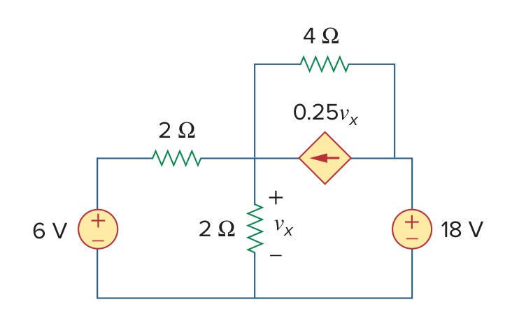
Alexander & Sadiku, 7th edition — the circuit for Example 4.7
Solution
The circuit consists of two voltage sources, a dependent current source and three resistors, and the question wants \(v_x\), the voltage across the 2 Ω resistor that runs down to the bottom rail. The dependent source is worth a quarter of \(v_x\) and sits across the 4 Ω resistor, its arrow pointing from right to left. We name the 2 Ω resistors r2a, beside the 6 V source, and r2b, the one \(v_x\) is marked across. We call the top of r2b a and the top of the 18 V source b, with the bottom rail as ground. A current source's current flows through it from its first node to its second, so the arrow gives j,b,a,vr2b/4.
e1,1,0,6
r2a,1,a,2
r2b,a,0,2
r4,a,b,4
j,b,a,vr2b/4
e2,b,0,18
Set Analysis to DC — direct current. Set Rounding in Settings to approx to n digits with n = 4.
Symbulator returns v_r2b = 7.5 V (the book's \(v_x\)).
AS7's Example 4.9
Open in app ↗Open in split view
Find the Thévenin equivalent of the circuit in the figure at terminals a-b.
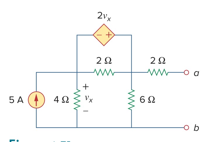
Alexander & Sadiku, 7th edition — the circuit for Example 4.9
Solution
The circuit consists of a 5 A source, a dependent voltage source and four resistors, and the question wants its Thévenin equivalent seen from terminals a and b. The dependent source is worth twice \(v_x\), the voltage across the 4 Ω resistor, and it sits across the 2 Ω resistor that joins the two upper nodes. We name that resistor r2a, the 2 Ω resistor leading to terminal a r2b, and the others after their values. We call the top of the 5 A source p and the top of the 6 Ω resistor q. The dependent source's positive mark is on q's side, so it is e,q,p,2*vr4. Terminal b is on the bottom rail, which we take as ground, so the terminals we name to the Find equivalent card are a and 0.
j,0,p,5
r4,p,0,4
r2a,p,q,2
e,q,p,2*vr4
r6,q,0,6
r2b,q,a,2
Open Find equivalent, choose Thévenin / Norton, and give the two terminals a and 0.
Symbulator returns vth = 20 V and req = 6 Ω (the book's \(R_{Th}\)).
AS7's Practice Problem 4.9
Open in app ↗Open in split view
Find the Thévenin equivalent circuit of the circuit in the figure to the left of the terminals.
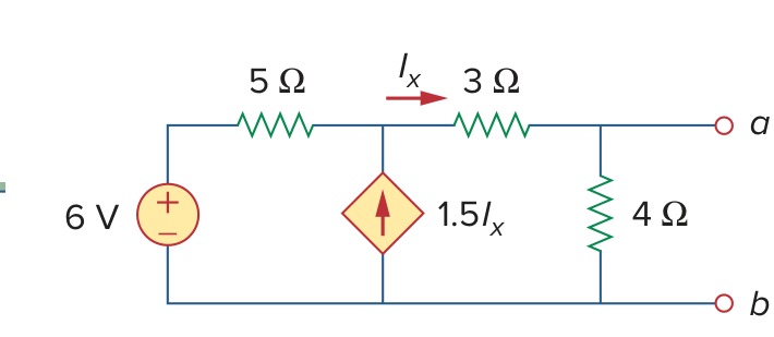
Alexander & Sadiku, 7th edition — the circuit for Practice Problem 4.9
Solution
The circuit consists of a 6 V source, a dependent current source and three resistors, and the question wants its Thévenin equivalent seen from the two terminals on the right. The dependent source is worth 1.5 times \(I_x\), the current to the right through the 3 Ω resistor, and its arrow points up. We call the node its arrow points into x and the top terminal a, with the bottom rail as ground, and name the resistors after their values. So \(I_x\) is the current through r3, and the dependent source is j,0,x,3*ir3/2.
e,1,0,6
r5,1,x,5
j,0,x,3*ir3/2
r3,x,a,3
r4,a,0,4
Open Find equivalent, choose Thévenin / Norton, and give the two terminals a and 0. Set Rounding in Settings to approx to n digits with n = 4.
Symbulator returns vth = 5.333 V and req = 0.4444 Ω (the book's \(R_{Th}\)).
AS7's Example 4.10
Open in app ↗Open in split view
Determine the Thévenin equivalent of the circuit in the figure at terminals a-b.

Alexander & Sadiku, 7th edition — the circuit for Example 4.10
Solution
The circuit has no independent source at all: a dependent current source worth twice \(i_x\), the current up through the 2 Ω resistor, in parallel with a 4 Ω and a 2 Ω resistor. The question wants its Thévenin equivalent at terminals a and b. With nothing to drive it, the circuit's open-circuit voltage is zero, so its Thévenin equivalent is a resistance alone, and the Find equivalent card's Resistance / impedance tool finds it. We take terminal b as ground and call terminal a a. We write the 2 Ω resistor from ground up to a, r2,0,a,2, so that its current is counted upward like \(i_x\), and the dependent source, whose arrow points down, as j,a,0,2*ir2.
j,a,0,2*ir2
r4,a,0,4
r2,0,a,2
Open Find equivalent, choose Resistance / impedance, and give the two terminals a and 0.
Symbulator returns req = -4 Ω (the book's \(R_{Th}\)).
AS7's Example 4.12
Open in app ↗Open in split view
Find (a) \(R_N\) and (b) \(I_N\) of the circuit in the figure at terminals a-b.
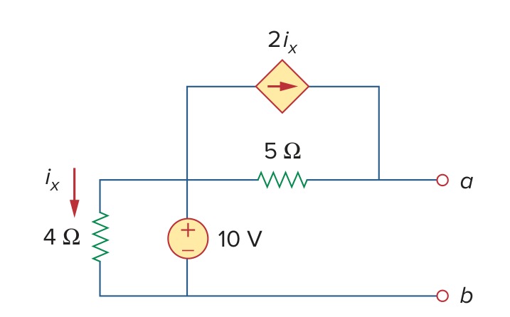
Alexander & Sadiku, 7th edition — the circuit for Example 4.12
Solution
The circuit consists of a 10 V source, a dependent current source and two resistors, and the question wants its Norton equivalent at terminals a and b: the current \(I_N\) and the resistance \(R_N\). The dependent source is worth twice \(i_x\), the current down through the 4 Ω resistor, and it sits across the 5 Ω resistor with its arrow pointing toward a. We call the top of the 10 V source p, take terminal b as ground and name the resistors after their values. So \(i_x\) is the current through r4, and the dependent source is j,p,a,2*ir4. The Find equivalent card's Thévenin / Norton tool reports both equivalents at once.
r4,p,0,4
e,p,0,10
r5,p,a,5
j,p,a,2*ir4
Open Find equivalent, choose Thévenin / Norton, and give the two terminals a and 0.
Symbulator returns (a) req = 5 Ω (the book's \(R_N\)) and (b) ino = 7 A (the book's \(I_N\)).
AS7's Example 4.13
Open in app ↗Open in split view
(a) Find the value of \(R_L\) for maximum power transfer in the circuit of the figure. (b) Find the maximum power.
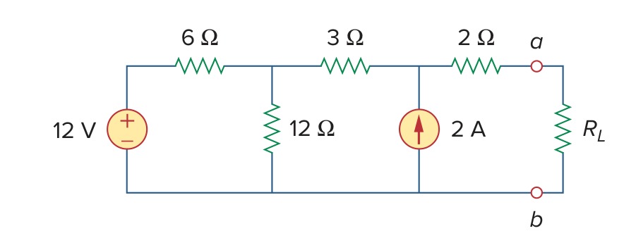
Alexander & Sadiku, 7th edition — the circuit for Example 4.13
Solution
The circuit consists of a 12 V source, a 2 A source and four resistors feeding a load \(R_L\) at terminals a and b, and the question wants the load that draws the most power and how much that power is. By the maximum power theorem that load equals the Thévenin resistance seen from a and b. So we describe the circuit without \(R_L\) and ask the Find equivalent card for the Thévenin equivalent there, which also reports the most power a load can draw. We number the nodes 1 to 3 from the source, call terminal a a and take terminal b as ground, and we name the resistors after their values.
e,1,0,12
r6,1,2,6
r12,2,0,12
r3,2,3,3
j,0,3,2
r2,3,a,2
Open Find equivalent, choose Thévenin / Norton, and give the two terminals a and 0. Set Rounding in Settings to approx to n digits with n = 4.
Symbulator returns (a) req = 9 Ω (the book's \(R_L\)) and (b) pmax = 13.44 W.
AS7's Example 4.18
Open in app ↗Open in split view
The circuit in the figure represents an unbalanced bridge. If the galvanometer has a resistance of 40 Ω, find the current through the galvanometer.

Alexander & Sadiku, 7th edition — the circuit for Example 4.18
Solution
A bridge is a pair of voltage dividers fed by one source, with a meter across the two midpoints. When the two dividers' ratios differ, current flows through the meter. The question wants that current, with the galvanometer taken as a 40 Ω resistance. We keep the figure's letters a and b for the two midpoints, call the top node 1 and take the bottom rail as ground. We name the galvanometer rg, written from a to b, and the other resistors after their values.
e,1,0,220
r3k,1,a,3'k
r1k,a,0,1'k
r400,1,b,400
r600,b,0,600
rg,a,b,40
Set Analysis to DC — direct current. Set Rounding in Settings to approx to n digits with n = 4.
Symbulator returns i_rg = -0.07476 A.
The value is negative, so the current flows through the galvanometer from b to a.
AS7's Example 5.1
Open in app ↗Open in split view
A 741 op amp has an open-loop voltage gain of 2 × 10⁵, input resistance of 2 MΩ, and output resistance of 50 Ω. The op amp is used in the circuit of the figure. (a) Find the closed-loop gain \(v_o/v_s\). (b) Determine current \(i\) when \(v_s\) = 2 V.

Alexander & Sadiku, 7th edition — the circuit for Example 5.1
Solution
An op amp can be modelled by what is inside it: a resistance between its two inputs, a dependent voltage source worth the open-loop gain times the voltage between them, and a resistance in series with its output. The question wants the closed-loop gain of an inverting amplifier built round that model, and a current at one input voltage. We write the model as three ordinary elements: ri for the 2 MΩ input resistance, ro for the 50 Ω output resistance, and e2 for the dependent source. The figure marks \(v_d\) positive at the bottom of the input resistance, so we write it from ground to node 1, ri,0,1,2'M, and \(v_d\) is its voltage drop vri. The dependent source is then e2,m,0,200000*vri, with m the node between it and ro. We leave the source as the symbol vs, so that the output comes back as a multiple of it, and call the input node in and the output out. We name the two outer resistors after their values, r10k and r20k.
e1,in,0,vs
r10k,in,1,10'k
ri,0,1,2'M
e2,m,0,200000*vri
ro,m,out,50
r20k,1,out,20'k
Set Analysis to DC — direct current. Set Rounding in Settings to approx (full precision).
(a) The closed-loop gain is the output over the source. We type it into Evaluate:
v_out/vsIt gives -1.9999698 (the book's \(v_o/v_s\)).
(b) The current \(i\) flows from node 1 to the output through the 20 kΩ feedback resistor. We type its name into Evaluate and the source's value into its Conditions box:
ir20kvs = 2It gives 0.00019999799 A (the book's \(i\)).
The book prints the gain as −1.9999699 and the current as 0.19999 mA. Its gain comes from an intermediate equation whose coefficients it rounds to whole numbers, and the circuit itself gives −1.9999698. Its current is cut at five figures, where the circuit gives 0.19999799 mA.
AS7's Example 5.10
Open in app ↗Open in split view
If \(v_1\) = 1 V and \(v_2\) = 2 V, find \(v_o\) in the op amp circuit of the figure.

Alexander & Sadiku, 7th edition — the circuit for Example 5.10
Solution
The circuit consists of three op amps: two inverting amplifiers, one for each input, and a summing amplifier that adds their outputs. The question wants the output \(v_o\) for the two input voltages given. An ideal op amp is the element o, whose three nodes are its non-inverting input, its inverting input and its output, in that order, and all three here have their non-inverting input on ground. We write the inputs as the sources e1 and e2, call the first two outputs a and b as the figure does and the summer's output out, and name the three inverting inputs n1, n2 and n3. We name the resistors after their values in kΩ, so the 6 kΩ feedback resistor is r6k.
e1,s1,0,1
r2k,s1,n1,2'k
o1,0,n1,a
r6k,n1,a,6'k
e2,s2,0,2
r4k,s2,n2,4'k
o2,0,n2,b
r8k,n2,b,8'k
r5k,a,n3,5'k
r15k,b,n3,15'k
o3,0,n3,out
r10k,n3,out,10'k
Set Analysis to DC — direct current. Set Rounding in Settings to approx to n digits with n = 4.
Symbulator returns v_out = 8.667 V (the book's \(v_o\)).
AS7's Practice Problem 5.13
Open in app ↗Open in split view
Determine the value of the external gain-setting resistor \(R_G\) required for the IA in the figure to produce a gain of 142 when R = 25 kΩ.
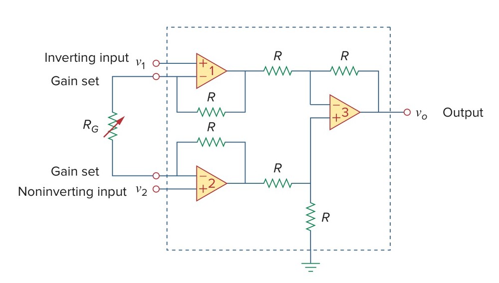
Alexander & Sadiku, 7th edition — the circuit for Practice Problem 5.13
Solution
An instrumentation amplifier is three op amps and seven resistors arranged to amplify the difference between two input voltages, with its gain set by a single external resistor, \(R_G\). The question wants the \(R_G\) that makes the gain 142 when every other resistor is 25 kΩ. The gain is the output over the difference of the inputs, so we leave the inputs as the symbols v1 and v2 and \(R_G\) as the symbol R_G, and the run returns the output as a formula in all three. An ideal op amp is the element o, with its non-inverting input first: the first takes v1 there and the second v2. We call the gain-set nodes g1 and g2, the first two outputs x1 and x2, and the third op amp's inputs p and n and its output out.
e1,in1,0,v1
e2,in2,0,v2
o1,in1,g1,x1
r1,x1,g1,25'k
rg,g1,g2,R_G
o2,in2,g2,x2
r2,x2,g2,25'k
r3,x1,n,25'k
r4,n,out,25'k
o3,p,n,out
r5,x2,p,25'k
r6,p,0,25'k
Set Analysis to DC — direct current. Set Rounding in Settings to approx to n digits with n = 4.
The gain is 142 when the output is 142 times the difference of the inputs. In the Solve card that is one equation and one unknown:
v_out=142*(v2-v1)R_GPress Solve equations.
The card returns R_G = 354.6 Ω.
AS7's Practice Problem 6.10
Open in app ↗Open in split view
Determine (a) \(v_C\), (b) \(i_L\), and (c) the energy stored in the capacitor and inductor in the circuit of the figure under dc conditions.
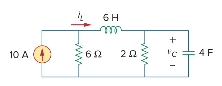
Alexander & Sadiku, 7th edition — the circuit for Practice Problem 6.10
Solution
The circuit consists of a 10 A source feeding a 6 Ω resistor and, through a 6 H inductor, a 2 Ω resistor and a 4 F capacitor. The question wants the capacitor's voltage, the inductor's current and the energy each stores once the circuit has settled. A DC run is that settled state: in it an inductor carries its current with no voltage across it and a capacitor passes no current. We call the two top nodes 1 and 2, take the bottom rail as ground, and name the resistors after their values. So \(v_C\) is the voltage at node 2 and \(i_L\) the current through l.
j,0,1,10
r6,1,0,6
l,1,2,6
r2,2,0,2
c,2,0,4
Set Analysis to DC — direct current. Set Rounding in Settings to approx to n digits with n = 4.
Symbulator returns (a) v_2 = 15 V (the book's \(v_C\)) and (b) i_l = 7.5 A.
(c) A capacitor stores half its capacitance times the square of its voltage. We type that into Evaluate with the 4 F capacitance and node 2's voltage:
4*v2^2/2It gives 450 J.
An inductor stores half its inductance times the square of its current. With the 6 H inductance:
6*il^2/2It gives 168.8 J.
AS7's Example 19.9
Open in app ↗Open in split view
The ABCD parameters of the two-port network in the figure are \(A\) = 4, \(B\) = 20 Ω, \(C\) = 0.1 S, \(D\) = 2. The output port is connected to a variable load for maximum power transfer. Find (a) \(R_L\) and (b) the maximum power transferred.

Alexander & Sadiku, 7th edition — the circuit for Example 19.9
Solution
The circuit consists of a 50 V source with a 10 Ω resistor feeding a two-port known only by its transmission parameters, and a variable load on the output port. The question wants the load that draws the most power and that power. A two-port known only by its parameters is an element of its own. For transmission parameters it is a, with its two port nodes and the four values as a bracketed term, [4,20,0.1,2]. We call the input port's top p and the output port's top q, with both bottoms on ground. We leave the load out and name its terminals, q and 0, to the Find equivalent card with Thévenin / Norton chosen. By the maximum power theorem the load that draws the most power is the Thévenin resistance, and the card reports that power too.
e,1,0,50
r10,1,p,10
a,p,q,[4,20,0.1,2]
Open Find equivalent, choose Thévenin / Norton, and give the two terminals q and 0.
Symbulator returns (a) req = 8 Ω (the book's \(R_L\)) and (b) pmax = 3.125 W (the book's \(P\)).
AS7's Practice Problem 19.9
Open in app ↗Open in split view
Find \(I_1\) and \(I_2\) if the transmission parameters for the two-port in the figure are \(A\) = 5, \(B\) = 10 Ω, \(C\) = 0.4 S, \(D\) = 1.
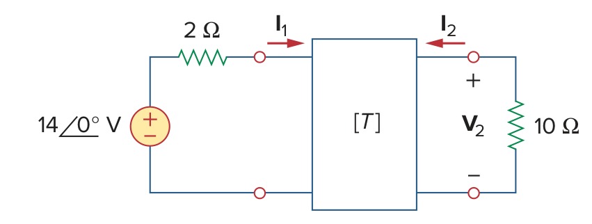
Alexander & Sadiku, 7th edition — the circuit for Practice Problem 19.9
Solution
The circuit consists of a 14 V source with a 2 Ω resistor feeding a two-port known by its transmission parameters, with a 10 Ω load on its output. The question wants the current into each port. The two-port is the element a, written with its two port nodes and the bracketed term [5,10,0.4,1]. We call the input port's top p and the output port's top q, with both bottoms on ground. The source is given as a phasor at 0°, which is a plain 14 V, so a DC run answers it. The two-port's card reports the current into each of its ports, counted into the top terminal as the book counts \(I_1\) and \(I_2\).
e,1,0,14
r2,1,p,2
a,p,q,[5,10,0.4,1]
r10,q,0,10
Set Analysis to DC — direct current.
Symbulator returns i_ap = 1 A (the book's \(I_1\)) and i_aq = -0.2 A (the book's \(I_2\)).
AS7's Example 19.12
Open in app ↗Open in split view
Evaluate \(V_2/V_s\) in the circuit of the figure.

Alexander & Sadiku, 7th edition — the circuit for Example 19.12
Solution
The circuit consists of a two-port given by its z parameters whose two lower terminals are joined and returned to ground through a 10 Ω resistor, fed through 5 Ω and loaded with 20 Ω. The question wants the output voltage over the source's. The 10 Ω resistor is itself a two-port in series with the first, but we need not combine them: we describe the circuit as drawn. A two-port known only by its parameters is an element of its own, z for z parameters. Its ports here do not share ground, so we write each port as a bracketed pair of terminals, top node then bottom, [a,m] and [b,m], followed by the four values. We call the input port's top a, the output port's top b and the joined bottoms m. We leave the source as the symbol vs, so that every answer comes back as a multiple of it. \(V_2\) is marked from b down to ground, so it is the voltage at b.
e,1,0,vs
r5,1,a,5
z,[a,m],[b,m],[12,8,8,20]
r10,m,0,10
r20,b,0,20
Set Analysis to DC — direct current. Set Rounding in Settings to approx to n digits with n = 4.
The ratio asked is the output over the source. We type it into Evaluate:
v_b/vsIt gives 0.3509 (the book's \(V_2/V_s\)).
AS7's Example 19.17 gains
Open in app ↗Open in split view
Consider the common-emitter amplifier circuit of the figure. Determine (a) the voltage gain, (b) current gain, (c) input impedance, and (d) output impedance using these h parameters: \(h_{ie}\) = 1 kΩ, \(h_{re}\) = 2.5 × 10⁻⁴, \(h_{fe}\) = 50, \(h_{oe}\) = 20 μS. (e) Find the output voltage \(V_o\).
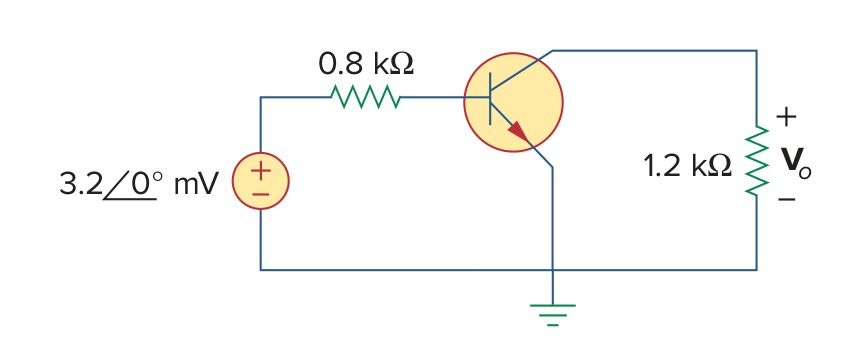
Alexander & Sadiku, 7th edition — the circuit for Example 19.17
Solution
The circuit consists of a transistor in common-emitter connection, modelled by its four h parameters, between a 3.2 mV source with 0.8 kΩ of source resistance and a 1.2 kΩ load. The question wants the gains, the impedances and the output voltage. A transistor known only by its h parameters is a two-port, and a two-port known only by its parameters is an element of its own, h, written with its two port nodes and the four values as a bracketed term, [1000,2.5e-4,50,20'u]. The emitter is common to both ports, so both ports' bottoms are ground. We call the base b and the collector c, name the source's resistance rs and the load rl. The source is given as a phasor at 0°, which is a plain 3.2 mV, so a DC run answers it. \(V_o\) is the voltage at c, and the two-port's card reports the current into each port, ihb and ihc.
e,1,0,3.2'm
rs,1,b,800
h,b,c,[1000,2.5e-4,50,20'u]
rl,c,0,1.2'k
Set Analysis to DC — direct current. Set Rounding in Settings to approx to n digits with n = 4.
(a) The voltage gain the book works out is the transistor's: its output voltage over its input voltage, the voltage at c over the voltage at b. We type that into Evaluate:
v_c/v_bIt gives -59.46 (the book's \(A_v\)).
(b) The current gain is the current into the output port over the current into the input port:
i_hc/i_hbIt gives 48.83 (the book's \(A_i\)).
(c) The input impedance is the input port's voltage over its current:
v_b/i_hbIt gives 985.4 Ω (the book's \(Z_{in}\)).
(d) The output impedance is the resistance seen into the output port with the load removed, so it is a run of its own, the next entry.
(e) The output voltage \(V_o\) is the voltage at c, read off the run: v_c = -0.105 V (the book's \(V_o\)).
The book prints \(V_o\) as −105.09 mV, carried through its own rounded arithmetic. The gain of the whole circuit, \(V_o\) over the 3.2 mV source, is −32.82, and −32.82 times 3.2 mV is −105.02 mV, which is what the run gives.
AS7's Example 19.17 output impedance
Open in app ↗Open in split view
(d) Determine the output impedance of the amplifier.
Alexander & Sadiku, 7th edition — the circuit for Example 19.17
Solution
This is the same amplifier with the load removed, and part (d) of the question wants the impedance seen looking back into the collector. That is the Thévenin resistance at the output, so we describe the circuit without rl and name c and 0 to the Find equivalent card with Thévenin / Norton chosen.
e,1,0,3.2'm
rs,1,b,800
h,b,c,[1000,2.5e-4,50,20'u]
Open Find equivalent, choose Thévenin / Norton, and give the two terminals c and 0. Set Rounding in Settings to approx to n digits with n = 4.
Symbulator returns (d) req = 76600 Ω (the book's \(Z_{out}\)).
Transients — TR
Eight transient problems follow. The pattern is the one you would follow by hand: run the circuit as it was before the switch moved in DC, read off the capacitor voltages and inductor currents, put those numbers in the fifth field of the c and l lines, and run the circuit as it is afterwards in TR. No time constant is computed and no solution form is selected. A switch that closes is a short circuit, the element s, and sequential switching is simply one more run. Three of the eight are op-amp circuits, one of them of second order.
AS7's Example 7.5
Open in app ↗Open in split view
In the circuit shown in the figure, find \(i_o\), \(v_o\), and \(i\) for all time, assuming that the switch was open for a long time.

Alexander & Sadiku, 7th edition — the circuit for Example 7.5
Solution
The circuit consists of a 10 V source feeding a 3 Ω resistor and an inductor in parallel with a 6 Ω resistor, and a switch that shorts the node between the 2 Ω and the 3 Ω to ground at \(t\) = 0. The question wants the inductor's current, the current in the 6 Ω and the voltage across the 3 Ω for all time, so before the switch closes as well as after. There are two intervals, and two runs. Before \(t\) = 0 the switch has been open for a long time and the circuit is steady. We describe it as it stands then, calling the source's top 1, the node between the 2 Ω and the 3 Ω a and the top of the inductor b. We name the resistors after their values and the inductor l, and run it in DC:
e,1,0,10
r2,1,a,2
r3,a,b,3
r6,b,0,6
l,b,0,2
Set Analysis to DC — direct current.
Symbulator returns i_l = 2 A (the book's \(i\)), v_r3 = 6 V (the book's \(v_o\)) and i_r6 = 0 A (the book's \(i_o\)).
Closing the switch joins a to ground. A closed switch is a short circuit, the element s, so we describe the second circuit as the first with s,a,0 added, and give the inductor the 2 A just found as its fifth field. We set the analysis to TR. The source stays in the description: the short takes its current, and nothing from it reaches the 3 Ω. \(i\) is the current through l and \(i_o\) the current through r6.
e,1,0,10
r2,1,a,2
r3,a,b,3
s,a,0
r6,b,0,6
l,b,0,2,2TROpen in app ↗Open in split view
Set Analysis to TR — transient / time domain. Set Rounding in Settings to approx to n digits with n = 4.
Here i_l is the book's \(i\) and i_r6 is the book's \(i_o\).
The run holds before \(t\) = 0 the values the first run gave: \(i\) = 2 A, \(i_o\) = 0 and \(v_o\) = 6 V. After it, \(v_o\) is the voltage from a to b. The switch holds a at zero, so \(v_o\) is the opposite of v_b, \(4e^{-t}\) V.
AS7's Example 7.13 to 4 s
Open in app ↗Open in split view
At \(t\) = 0, switch 1 in the figure is closed, and switch 2 is closed 4 s later. (a) Find \(i(t)\) for \(t\) > 0. (b) Calculate \(i\) for \(t\) = 2 s and \(t\) = 5 s.

Alexander & Sadiku, 7th edition — the circuit for Example 7.13
Solution
The circuit consists of an inductor, a 40 V source that switch 1 connects at \(t\) = 0, and a 10 V source that switch 2 connects 4 s later. The question wants the inductor's current for all \(t\) > 0 and its value at two instants. Before \(t\) = 0 both switches are open and no source reaches the inductor, so it carries no current and needs no first run. There are two intervals after that, and two runs. In the first, only switch 1 is closed, which puts the 40 V source, the 4 Ω, the 6 Ω and the inductor in one loop. In TR a source with a plain numerical value is a step that begins at \(t\) = 0, so switch 1 needs no element. We call the source's top 1, the node P of the figure p and the top of the inductor x. We write the inductor without a fifth field and set the analysis to TR. \(i\) is the current through l.
e1,1,0,40
r4,1,p,4
r6,p,x,6
l,x,0,5
Set Analysis to TR — transient / time domain. Set Rounding in Settings to approx to n digits with n = 4.
(a) is i_l (the book's \(i\)).
(b) The question asks for \(i\) at \(t\) = 2 s, which falls in this interval. We read it from the answer with Evaluate:
i_lt = 2It gives 3.927 A (the book's \(i(2)\)).
Switch 2 closes at \(t\) = 4 s, and the current at that instant is where the next interval starts. We read it the same way:
i_lt = 4It gives 3.999 A (the book's \(i(4)\)).
AS7's Example 7.13 after 4 s
Open in app ↗Open in split view
(a) Find \(i(t)\) for \(t\) ≥ 4 s, and (b) calculate \(i\) for \(t\) = 5 s. (Time is measured from the closing of switch 2.)
Alexander & Sadiku, 7th edition — the circuit for Example 7.13
Solution
This is the second interval of the same problem. Switch 2 has closed too, adding the 2 Ω and the 10 V source between node p and ground. We call the node between them q, and name the two sources e1 and e2. The inductor's current cannot jump, so it starts this interval at the value the first run reached at 4 s, \(4 - 4e^{-8}\). We write that as the expression 4-4*exp(-8) in its fifth field, which keeps it exact. This run's \(t\) = 0 is the instant switch 2 closes, so the book's \(t\) is this run's \(t\) plus 4 s.
e1,1,0,40
r4,1,p,4
r2,p,q,2
e2,q,0,10
r6,p,x,6
l,x,0,5,4-4*exp(-8)
Set Analysis to TR — transient / time domain. Set Rounding in Settings to approx to n digits with n = 4.
(a) is i_l (the book's \(i\)).
(b) The question asks for \(i\) at \(t\) = 5 s, which is 1 s after switch 2 closes. We read it from the answer with Evaluate:
i_lt = 1It gives 3.021 A (the book's \(i(5)\)).
AS7's Example 7.14
Open in app ↗Open in split view
For the op amp circuit in the figure, find \(v_o\) for \(t\) > 0, given that \(v(0)\) = 3 V. Let \(R_f\) = 80 kΩ, \(R_1\) = 20 kΩ, and \(C\) = 5 μF.

Alexander & Sadiku, 7th edition — the circuit for Example 7.14
Solution
The circuit consists of an op amp whose input capacitor holds 3 V, with a resistor from the capacitor to ground and a feedback resistor. There is no source, so the question wants the output as the capacitor discharges. An ideal op amp is the element o, whose three nodes are its non-inverting input, its inverting input and its output. Its non-inverting input is on ground. We keep the figure's node numbers 1 and 2, call the output out, and name the resistors r1 and rf after the book's \(R_1\) and \(R_f\). The capacitor's voltage \(v\) is positive on node 1's side, so we write it c,1,2,5'u,3, with the 3 V as its fifth field. We set the analysis to TR.
r1,1,0,20'k
c,1,2,5'u,3
o,0,2,out
rf,2,out,80'k
Set Analysis to TR — transient / time domain.
v_out is the book's \(v_o\).
AS7's Example 7.16
Open in app ↗Open in split view
Find the step response \(v_o(t)\) for \(t\) > 0 in the op amp circuit of the figure. Let \(v_i\) = \(2u(t)\) V, \(R_1\) = 20 kΩ, \(R_f\) = 50 kΩ, \(R_2\) = \(R_3\) = 10 kΩ, \(C\) = 2 μF.
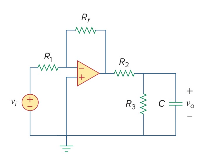
Alexander & Sadiku, 7th edition — the circuit for Example 7.16
Solution
The circuit consists of an inverting amplifier whose output feeds a 10 kΩ resistor into a second 10 kΩ and a capacitor in parallel. The question wants the capacitor's voltage after a 2 V step at the input. In TR a source with a plain numerical value is a step that begins at \(t\) = 0, so \(2u(t)\) is the source e,1,0,2. An ideal op amp is the element o, with its non-inverting input first, here on ground. We call its inverting input n, its output a and the top of the capacitor p, and name the resistors after the book's \(R_1\), \(R_f\), \(R_2\) and \(R_3\). The capacitor holds no charge at the step, so it has no fifth field. We set the analysis to TR. \(v_o\) is the voltage at node p.
e,1,0,2
r1,1,n,20'k
o,0,n,a
rf,n,a,50'k
r2,a,p,10'k
r3,p,0,10'k
c,p,0,2'u
Set Analysis to TR — transient / time domain. Set Rounding in Settings to approx to n digits with n = 4.
v_p is the book's \(v_o\).
AS7's Practice Problem 8.6
Open in app ↗Open in split view
Refer to the circuit in the figure. Find \(v(t)\) for \(t\) > 0.

Alexander & Sadiku, 7th edition — the circuit for Practice Problem 8.6
Solution
The circuit consists of a 4.5 A source, which a switch cuts off at \(t\) = 0, in parallel with a 20 Ω resistor, a 10 H inductor and a 4 mF capacitor. The question wants the voltage across the three afterwards. There are two intervals, and two runs. Before \(t\) = 0 the source has fed the three for a long time and the circuit is steady. We describe it as it stands then, all four elements between node 1 and ground, and run it in DC for the inductor's current and the capacitor's voltage:
j,0,1,4.5
r20,1,0,20
l,1,0,10
c,1,0,4'm
Set Analysis to DC — direct current.
Symbulator returns i_l = 4.5 A (the book's \(i_L(0)\)) and v_1 = 0 V (the book's \(v(0)\)).
Opening the switch removes the source and leaves the resistor, the inductor and the capacitor to release what they hold. We describe those three with the same names and give the inductor and the capacitor the 4.5 A and 0 V just found as their fifth fields. We set the analysis to TR. \(v\) is the voltage at node 1.
r20,1,0,20
l,1,0,10,4.5
c,1,0,4'm,0TROpen in app ↗Open in split view
Set Analysis to TR — transient / time domain.
v_1 is the book's \(v\).
AS7's Practice Problem 8.10
Open in app ↗Open in split view
For \(t\) > 0, obtain \(v_o(t)\) in the circuit of the figure.

Alexander & Sadiku, 7th edition — the circuit for Practice Problem 8.10
Solution
The circuit is a ladder of two resistors and two capacitors switched onto a 20 V step, and the question wants the voltage across the second resistor. In TR a source with a plain numerical value is a step that begins at \(t\) = 0, so \(20u(t)\) is the source e,s,0,20. We call the source's top s and keep the figure's \(v_1\) and \(v_2\) as nodes 1 and 2. We name the resistors ra and rb and the capacitors c1 and c2, writing the capacitances as the fractions the book gives, 1/2 and 1/3. Neither capacitor holds a charge. We set the analysis to TR.
e,s,0,20
ra,s,1,1
c1,1,0,1/2
rb,1,2,1
c2,2,0,1/3
Set Analysis to TR — transient / time domain.
The voltage \(v_o\) is marked across the second 1 Ω resistor, positive on node 1's side, so it is the difference of the two node voltages. We type it into Evaluate:
v_1 - v_2It gives:
AS7's Example 8.11
Open in app ↗Open in split view
In the op amp circuit of the figure, find \(v_o(t)\) for \(t\) > 0 when \(v_s\) = \(10u(t)\) mV. Let \(R_1\) = \(R_2\) = 10 kΩ, \(C_1\) = 20 μF, and \(C_2\) = 100 μF.

Alexander & Sadiku, 7th edition — the circuit for Example 8.11
Solution
The circuit consists of an op amp wired as a voltage follower, fed through two resistors, with one capacitor from the junction of the resistors to the output and another from the follower's input to ground. The question wants the output after a 10 mV step. In TR a source with a plain numerical value is a step that begins at \(t\) = 0, so we write it e,in,0,10'm. An ideal op amp is the element o, with its non-inverting input first: here that input is node 2 and the inverting input is the output itself, so it is o,2,out,out. We keep the figure's node numbers 1 and 2, call the output out, and name the elements after the book's \(R_1\), \(R_2\), \(C_1\) and \(C_2\). Neither capacitor holds a charge. We set the analysis to TR.
e,in,0,10'm
r1,in,1,10'k
r2,1,2,10'k
c1,2,0,20'u
c2,1,out,100'u
o,2,out,out
Set Analysis to TR — transient / time domain. Set Rounding in Settings to approx to n digits with n = 4.
v_out is the book's \(v_o\).
The run gives the output in volts. In millivolts it reads \(10 - e^{-t}(10\cos 2t + 5\sin 2t)\).
Sinusoidal steady state — AC
Seventeen problems are in the sinusoidal steady state. Where the book gives its impedances in ohms they go in as written, complex ones included, and the frequency never enters: omega is left as a symbol in the ω — angular frequency box and nothing depends on it. Where the book gives henries and farads instead, the frequency goes in that box and the conversion to impedance is the solver's. Two filter problems leave the frequency as a symbol on purpose, and find their corner frequency in the Solve card. Two circuits run at more than one frequency at once, and take one run per frequency, which is superposition done the way the book does it. The powers of an AC run are on every card, and a power factor is one entry in the Mini-Tools card.
AS7's Example 9.14
Open in app ↗Open in split view
For the RL circuit shown in the figure, calculate the amount of phase shift produced at 2 kHz.
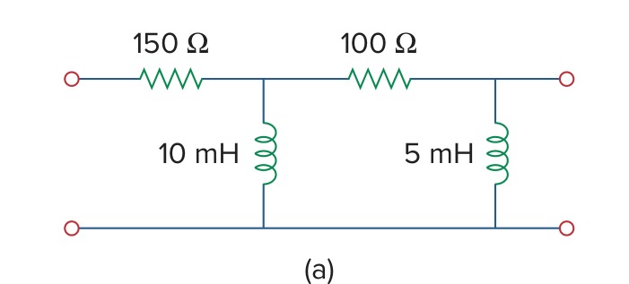
Alexander & Sadiku, 7th edition — the circuit for Example 9.14
Solution
The circuit is a ladder of two resistors and two inductors between an input and an output, and the question wants the phase of the output relative to the input at 2 kHz. We leave the input as the symbol vi, so that every answer comes back as a multiple of it. The inductors are given as inductances, so we write them as they are, l10 and l5, and put the angular frequency in the ω — angular frequency box. That is 2π times 2000 Hz, which we type as 4000*pi. We call the input node in, the node between the two rungs 1 and the output out, and name the resistors after their values.
e,in,0,vi
r150,in,1,150
l10,1,0,10'm
r100,1,out,100
l5,out,0,5'm
Set Analysis to AC — alternating current. Put 12566.4 in the ω — angular frequency box. Set Rounding in Settings to approx to n digits with n = 4.
The phase shift is the angle of the output over the input. We type that ratio into Evaluate:
v_out/viIt gives -0.03264 + 0.1877j (0.1905∠99.87°, the book's \(V_o/V_i\)).
The ratio's angle is the phase shift: the output leads the input by about 100°, at about 19% of its amplitude.
AS7's Example 10.2
Open in app ↗Open in split view
Compute \(V_1\) and \(V_2\) in the circuit of the figure.
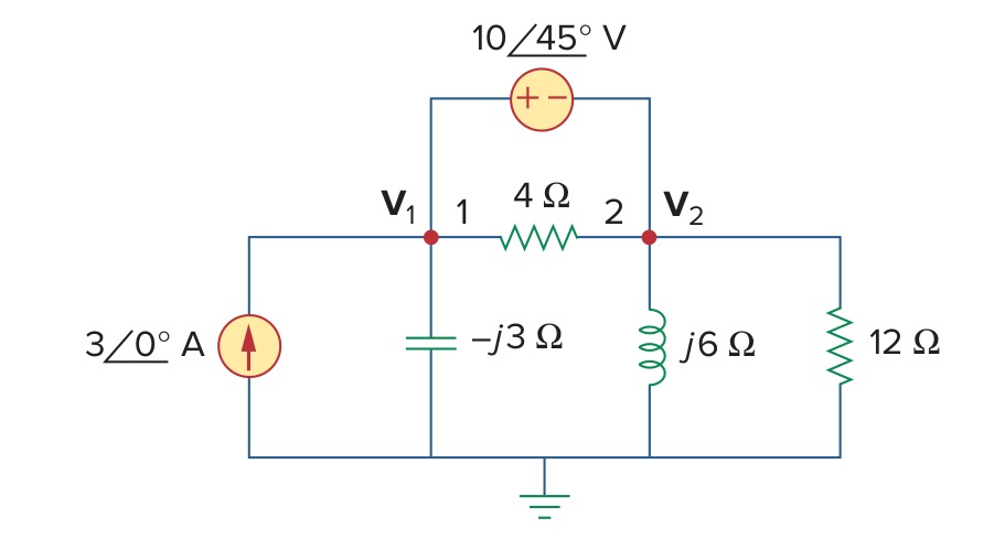
Alexander & Sadiku, 7th edition — the circuit for Example 10.2
Solution
The circuit consists of a current source, a voltage source between two nodes, and four impedances given in ohms. The question wants the phasor voltages at the two top nodes, \(V_1\) and \(V_2\). Every impedance is given in ohms, so we write each one as a resistor with its value, -3j for the capacitor and 6j for the inductor, and leave the frequency as the symbol omega, which no value uses. We keep the figure's node numbers 1 and 2. A source's value is a phasor, its magnitude and its angle in degrees, so the voltage source is (10∠45°), positive on node 1's side, and the current source is j,0,1,3, its arrow pointing up into node 1.
j,0,1,3
rc,1,0,-3j
e,1,2,(10∠45°)
r4,1,2,4
rl,2,0,6j
r12,2,0,12
Set Analysis to AC — alternating current. Leave omega in the ω — angular frequency box, since nothing here depends on the frequency. Set Rounding in Settings to approx to n digits with n = 4.
Symbulator returns v_1 = 8.614 - 24.3j V (25.78∠-70.48°) and v_2 = 1.543 - 31.37j V (31.41∠-87.18°).
AS7's Example 10.4
Open in app ↗Open in split view
Solve for \(V_o\) in the circuit of the figure.
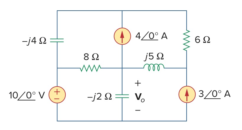
Alexander & Sadiku, 7th edition — the circuit for Example 10.4
Solution
The circuit consists of a voltage source, two current sources and five impedances in four meshes, and the question wants the voltage \(V_o\) across the −j2 Ω capacitor. The whole top edge of the figure is one wire, which we call node t. We call the top of the 10 V source l, the centre of the figure c and the right-hand node below the 6 Ω r, with the bottom rail as ground. Every impedance is given in ohms, so each is a resistor with its value: rc4 and rc2 for the two capacitors, rl for the inductor, r8 and r6 for the resistors. The 4 A source's arrow points up from c to t, and the 3 A source's up from ground to r. \(V_o\) is the voltage at node c.
e,l,0,10
rc4,t,l,-4j
r8,l,c,8
j1,c,t,4
rl,c,r,5j
r6,t,r,6
j2,0,r,3
rc2,c,0,-2j
Set Analysis to AC — alternating current. Leave omega in the ω — angular frequency box, since nothing here depends on the frequency. Set Rounding in Settings to approx to n digits with n = 4.
Symbulator returns v_c = -7.214 - 6.566j V (9.754∠-137.7°, the book's \(V_o\)).
AS7's Example 10.6
Open in app ↗Open in split view
Find \(v_o\) of the circuit of the figure.
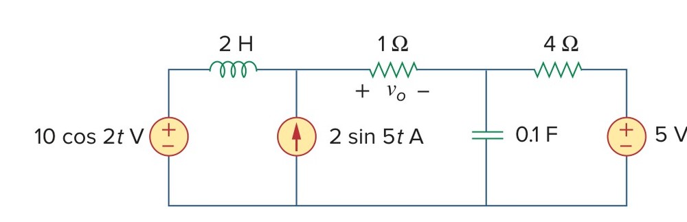
Alexander & Sadiku, 7th edition — the circuit for Example 10.6
Solution
The circuit consists of three sources at three different frequencies, a 10 cos 2\(t\) V source, a 2 sin 5\(t\) A source and a 5 V dc source, feeding an inductor, a capacitor and two resistors. The question wants the voltage \(v_o\) across the 1 Ω resistor. A DC or an AC run works at one frequency, and this circuit has three, so the answer takes one run per source. In each run the other two sources are switched off, which is what superposition does: a voltage source at zero is a short, and a current source at zero is an open. We call the top of the 10 V source a, the top of the current source b, the top of the capacitor c and the top of the 5 V source d, with the bottom rail as ground. We name the sources e1, j and e2 and the resistors after their values, so \(v_o\) is the voltage drop across r1. The first run keeps the 5 V source alone. DC sees the inductor as a short and the capacitor as an open, and the other two sources get the value 0:
e1,a,0,0
l,a,b,2
j,0,b,0
r1,b,c,1
c,c,0,0.1
r4,c,d,4
e2,d,0,5
Set Analysis to DC — direct current.
Symbulator returns v_r1 = -1 V (the book's \(v_1\)).
The second run keeps the 10 cos 2\(t\) V source alone, at its frequency of 2 rad/s. In AC a source's value is its phasor, and a cosine of amplitude 10 with no phase is 10. The inductor and the capacitor are given in henries and farads, so the frequency goes in the ω — angular frequency box. The current source and the 5 V source get the value 0:
e1,a,0,10
l,a,b,2
j,0,b,0
r1,b,c,1
c,c,0,0.1
r4,c,d,4
e2,d,0,0
AC at 2 rad/sOpen in app ↗Open in split view
Set Analysis to AC — alternating current. Put 2 in the ω — angular frequency box. Set Rounding in Settings to approx to n digits with n = 4.
Symbulator returns v_r1 = 2.146 - 1.279j V (2.498∠-30.78°, the book's \(V_2\)).
The third run keeps the 2 sin 5\(t\) A source alone, at 5 rad/s. Phasors are measured against a cosine, and 2 sin 5\(t\) is 2 cos(5\(t\) − 90°), so the source's value is the phasor (2∠-90°). The two voltage sources get the value 0, and the frequency is 5:
e1,a,0,0
l,a,b,2
j,0,b,(2∠-90°)
r1,b,c,1
c,c,0,0.1
r4,c,d,4
e2,d,0,0
AC at 5 rad/sOpen in app ↗Open in split view
Set Analysis to AC — alternating current. Put 5 in the ω — angular frequency box. Set Rounding in Settings to approx to n digits with n = 4.
Symbulator returns v_r1 = 0.4878 - 2.276j V (2.328∠-77.91°, the book's \(V_3\)).
Each run's phasor is one term of \(v_o\), at its own frequency. Written back in time and added, \(v_o\) = −1 + 2.498 cos(2\(t\) − 30.78°) + 2.328 cos(5\(t\) − 77.91°) V, and the last term is 2.328 sin(5\(t\) + 12.09°) V. The book prints that term as 2.33 sin(5\(t\) + 10°): its own expression for it gives an angle of −77.91°, not the −80° it prints. Its −30.79° for the second term rounds the last digit the other way.
AS7's Practice Problem 10.6
Open in app ↗Open in split view
Calculate \(v_o\) in the circuit of the figure.

Alexander & Sadiku, 7th edition — the circuit for Practice Problem 10.6
Solution
The circuit consists of a 75 sin 5\(t\) V source and a 6 cos 10\(t\) A source, at two different frequencies, feeding an 8 Ω resistor, a 0.2 F capacitor and a 1 H inductor. The question wants the voltage \(v_o\) across the capacitor. An AC run works at one frequency, so the answer takes one run per source, with the other source switched off: a voltage source at zero is a short, and a current source at zero is an open. We call the top of the voltage source a and the top of the capacitor b, with the bottom rail as ground, so \(v_o\) is the voltage at node b. The first run keeps the voltage source alone, at 5 rad/s. Phasors are measured against a cosine, and 75 sin 5\(t\) is 75 cos(5\(t\) − 90°), so its value is the phasor (75∠-90°). The current source gets the value 0:
e,a,0,(75∠-90°)
r8,a,b,8
c,b,0,0.2
l,b,0,1
j,0,b,0
Set Analysis to AC — alternating current. Put 5 in the ω — angular frequency box. Set Rounding in Settings to approx to n digits with n = 4.
Symbulator returns v_b = -11.44 - 1.787j V (11.58∠-171.1°, the book's \(V_1\)).
The second run keeps the 6 cos 10\(t\) A source alone, at 10 rad/s, its value the plain amplitude 6, and the voltage source gets the value 0:
e,a,0,0
r8,a,b,8
c,b,0,0.2
l,b,0,1
j,0,b,6
AC at 10 rad/sOpen in app ↗Open in split view
Set Analysis to AC — alternating current. Put 10 in the ω — angular frequency box. Set Rounding in Settings to approx to n digits with n = 4.
Symbulator returns v_b = 0.2069 - 3.144j V (3.151∠-86.24°, the book's \(V_2\)).
The two phasors are the terms of \(v_o\) at their own frequencies. Written back in time and added, \(v_o\) = 11.58 cos(5\(t\) − 171.1°) + 3.151 cos(10\(t\) − 86.24°) V. The first term is 11.58 sin(5\(t\) − 81.1°) V, the book's 11.577 sin(5\(t\) − 81.12°) to four figures. The book prints the second amplitude as 3.154, where the circuit gives 3.151.
AS7's Example 10.9
Open in app ↗Open in split view
Find the Thévenin equivalent of the circuit in the figure as seen from terminals a-b.

Alexander & Sadiku, 7th edition — the circuit for Example 10.9
Solution
The circuit consists of a 15 A source, a dependent current source and two impedances, and the question wants its Thévenin equivalent at terminals a and b. The dependent source is worth half of \(I_o\), the current down through the 2 Ω and −j4 Ω branch. Nothing else connects between the 2 Ω and the −j4 Ω, so we write them as one impedance, r1 worth 2-4j, and \(I_o\) is its current ir1. Likewise the 4 Ω and j3 Ω become r2 worth 4+3j. We call the top of the 15 A source 1, keep a for the top terminal and take terminal b as ground. The dependent source's arrow points down, so it is j2,a,0,ir1/2.
j1,0,1,15
r1,1,0,2-4j
r2,1,a,4+3j
j2,a,0,ir1/2
Open Find equivalent, choose Thévenin / Norton, and give the two terminals a and 0. Set Analysis to AC — alternating current. Leave omega in the ω — angular frequency box, since nothing here depends on the frequency. Set Rounding in Settings to approx to n digits with n = 4.
Symbulator returns vth = -55j V (55.00∠-90.00°) and zeq = 4 - 0.6667j Ω (4.055∠-9.462°, the book's \(Z_{Th}\)).
AS7's Practice Problem 10.9
Open in app ↗Open in split view
Determine the Thévenin equivalent of the circuit in the figure as seen from the terminals a-b.
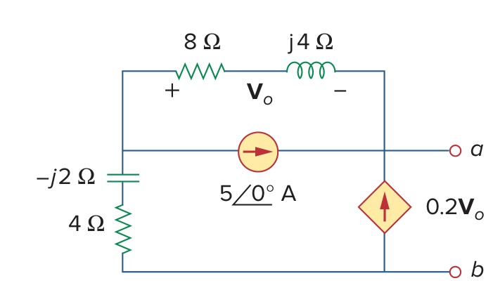
Alexander & Sadiku, 7th edition — the circuit for Practice Problem 10.9
Solution
The circuit consists of a 5 A source, a dependent current source worth 0.2 times \(V_x\) and two impedances, and the question wants its Thévenin equivalent at terminals a and b. \(V_x\) is marked across the 8 Ω and j4 Ω in series, which nothing else joins, so we write that pair as one impedance, r2 worth 8+4j, and \(V_x\) is its voltage drop vr2. The −j2 Ω and 4 Ω on the left become r1 worth 4-2j. We call their top 1, keep a for the top terminal and take terminal b as ground. The 5 A source's arrow points from 1 to a, and the dependent source's up from ground to a, so it is j2,0,a,vr2/5.
r1,1,0,4-2j
r2,1,a,8+4j
j1,1,a,5
j2,0,a,vr2/5
Open Find equivalent, choose Thévenin / Norton, and give the two terminals a and 0. Set Analysis to AC — alternating current. Leave omega in the ω — angular frequency box, since nothing here depends on the frequency. Set Rounding in Settings to approx to n digits with n = 4.
Symbulator returns vth = 2.162 + 7.027j V (7.352∠72.90°) and zeq = 4.432 - 0.5946j Ω (4.472∠-7.640°, the book's \(Z_{Th}\)).
AS7's Example 10.10
Open in app ↗Open in split view
Obtain current \(I_o\) in the figure.

Alexander & Sadiku, 7th edition — the circuit for Example 10.10
Solution
The circuit consists of a voltage source, a current source and four branches of impedances, and the question wants the current \(I_o\) down through the right-hand branch. The top wire of the figure runs from the 5 Ω resistor to terminal a, so it is one node, which we call a, with terminal b and the bottom rail as ground. We call the node between the 5 Ω and the source l and the centre of the figure m. Impedances in series with nothing between them we write as one: r8 worth 8-2j, r10 worth 10+4j, and ro worth 20+15j for the branch that carries \(I_o\). The source is the phasor (40∠90°). The 3 A source's arrow points up, from m to a.
r5,a,l,5
e,l,0,(40∠90°)
r8,l,m,8-2j
j,m,a,3
r10,m,0,10+4j
ro,a,0,20+15j
Set Analysis to AC — alternating current. Leave omega in the ω — angular frequency box, since nothing here depends on the frequency. Set Rounding in Settings to approx to n digits with n = 4.
Symbulator returns i_ro = 1.147 + 0.9118j A (1.465∠38.48°, the book's \(I_o\)).
AS7's Example 10.11
Open in app ↗Open in split view
Determine \(v_o(t)\) for the op amp circuit in the figure if \(v_s\) = 3 cos 1000\(t\) V.
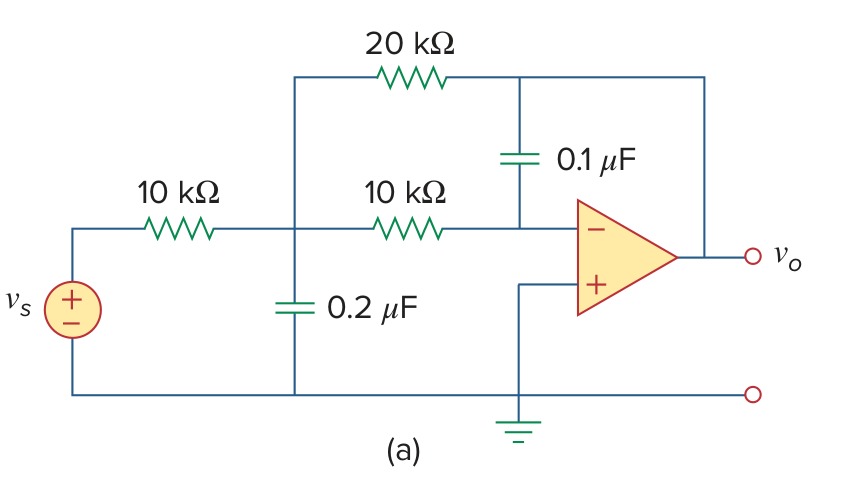
Alexander & Sadiku, 7th edition — the circuit for Example 10.11
Solution
The circuit consists of an op amp fed through a network of three resistors and two capacitors, and the question wants the output for a 3 V cosine at 1000 rad/s. The capacitors are given as capacitances, so we write them as they are and put 1000 in the ω — angular frequency box. The source is a cosine of amplitude 3 with no phase, so its value is 3. An ideal op amp is the element o, with its non-inverting input first, here on ground. We call the source's top s, the junction of the three resistors 1, the inverting input n and the output out, and name the resistors and capacitors after their places: r1 and r2 in the input path, rf in feedback, c1 to ground and c2 from n to the output.
e,s,0,3
r1,s,1,10'k
c1,1,0,0.2'u
r2,1,n,10'k
rf,1,out,20'k
c2,n,out,0.1'u
o,0,n,out
Set Analysis to AC — alternating current. Put 1000 in the ω — angular frequency box. Set Rounding in Settings to approx to n digits with n = 4.
Symbulator returns v_out = 0.5294 + 0.8824j V (1.029∠59.04°, the book's \(V_o\)).
As a function of time that is \(v_o(t)\) = 1.029 cos(1000\(t\) + 59.04°) V.
AS7's Practice Problem 10.13
Open in app ↗Open in split view
Obtain \(v_o\) and \(i_o\) in the circuit of the figure.
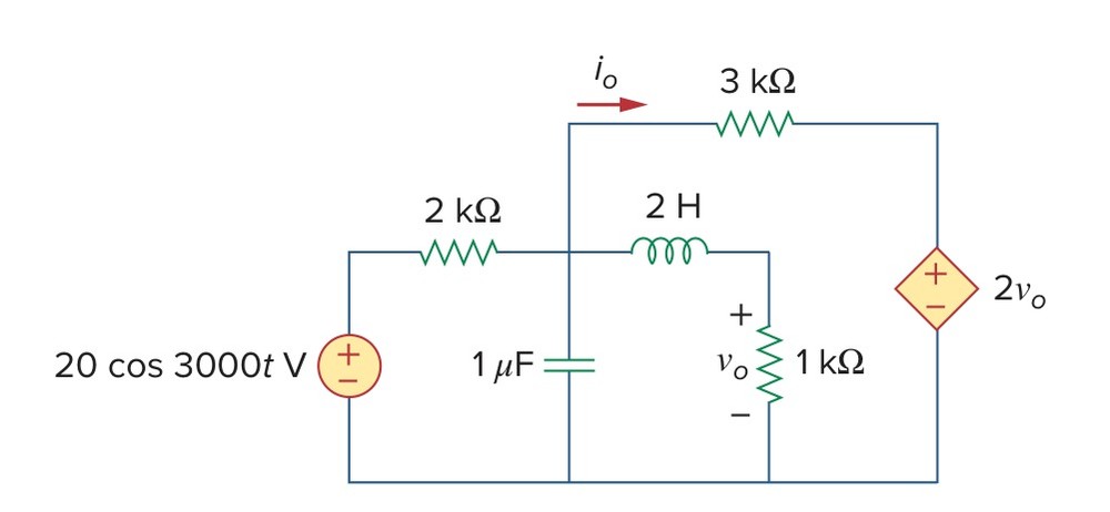
Alexander & Sadiku, 7th edition — the circuit for Practice Problem 10.13
Solution
The circuit consists of a 20 V cosine source at 3000 rad/s, a dependent voltage source worth twice \(v_o\), a capacitor, an inductor and three resistors. The question wants \(v_o\), the voltage across the 1 kΩ resistor, and \(i_o\), the current through the 3 kΩ. We call the source's top s, the node where the 2 kΩ, the capacitor, the inductor and the 3 kΩ meet 1, the top of the 1 kΩ 2 and the top of the dependent source d. We name the resistors after their values, so \(v_o\) is the drop across r1k and the dependent source's value is 2*vr1k. The inductor and the capacitor are given in henries and farads, so we put 3000 in the ω — angular frequency box. \(i_o\) flows from node 1 toward the dependent source, which is how r3k,1,d counts it.
e,s,0,20
r2k,s,1,2'k
c,1,0,1'u
l,1,2,2
r1k,2,0,1'k
r3k,1,d,3'k
e2,d,0,2*vr1k
Set Analysis to AC — alternating current. Put 3000 in the ω — angular frequency box. Set Rounding in Settings to approx to n digits with n = 4.
Symbulator returns v_2 = -0.4846 - 0.2303j V (0.5365∠-154.6°, the book's \(V_o\)) and i_r3k = 0.0006222 - 0.0008924j A (0.001088∠-55.12°, the book's \(I_o\)).
As functions of time those are \(v_o\) = 536.5 cos(3000\(t\) − 154.6°) mV and \(i_o\) = 1.088 cos(3000\(t\) − 55.12°) mA. The book's answer comes from a PSpice run and prints the first amplitude as 536.4 mV. The circuit gives 536.55 mV, which is 536.5 at four digits.
AS7's Example 11.4
Open in app ↗Open in split view
Determine the average power generated by each source and the average power absorbed by each passive element in the circuit of the figure.

Alexander & Sadiku, 7th edition — the circuit for Example 11.4
Solution
The circuit consists of a current source and a voltage source feeding a resistor, an inductor and a capacitor, and the question wants the average power each source generates and each passive element absorbs. Every card of an AC run carries its element's average power, so one run answers the whole question. We call the top of the current source 1, the top of the inductor m and the top of the voltage source r. The impedances are given in ohms, so we write each as a resistor with its value: r20, rl worth 10j and rc worth -5j. The voltage source is the phasor (60∠30°). The question gives peak values, so RMS stays off.
j,0,1,4
r20,1,m,20
rl,m,0,10j
rc,m,r,-5j
e,r,0,(60∠30°)
Set Analysis to AC — alternating current. Leave omega in the ω — angular frequency box, since nothing here depends on the frequency. Set Rounding in Settings to approx to n digits with n = 4.
On a passive element the card reads the average power consumed, the answer p. On a source it reads the power delivered, which is the negative of its p.
Symbulator returns -p_j = 367.8 W, -p_e = -207.8 W, p_r20 = 160 W (the book's \(P_2\)), p_rl = 0 W (the book's \(P_3\)) and p_rc = 0 W (the book's \(P_4\)).
The voltage source's delivered power is negative: it absorbs 207.8 W, which the current source supplies along with the resistor's 160 W.
AS7's Example 11.14
Open in app ↗Open in split view
In the circuit of the figure, \(Z_1\) = 60∠−30° Ω and \(Z_2\) = 40∠45° Ω. Calculate the total: (a) apparent power, (b) real power, (c) reactive power, and (d) pf, supplied by the source and seen by the source.

Alexander & Sadiku, 7th edition — the circuit for Example 11.14
Solution
The circuit is a source feeding two impedances in parallel, each given as a magnitude and an angle, and the question wants the source's apparent, real and reactive power and its power factor. We write the two impedances as they are given, as phasors in ohms, (60∠-30°) and (40∠45°). A resistor with a complex value is an impedance, so we name them r1 and r2 after the book's \(Z_1\) and \(Z_2\). The source is an rms value, so we tick RMS, and every power the run reports is then in terms of rms values, as the book's are.
e,1,0,(120∠10°)
r1,1,0,(60∠-30°)
r2,1,0,(40∠45°)
Set Analysis to AC — alternating current. Leave omega in the ω — angular frequency box, since nothing here depends on the frequency. Tick RMS phasors in Settings, since the book's source is given in rms. Set Rounding in Settings to approx to n digits with n = 4.
(b) and (c) are read off the source's card, which reports the real and the reactive power it delivers.
Symbulator returns -p_e = 462.4 W and -q_e = 134.6 var.
(a) The apparent power is the magnitude of the complex power the source delivers. We type it into Evaluate:
abs(s_e)It gives 481.6 VA (the book's \(|S|\)).
(d) The power factor is a question for the Mini-Tools card. We choose pf — power factor in its Tool menu and give it the source's name, which asks for the power factor of the power the source delivers:
ePress Run.
The card returns the power factor 0.9602 lagging.
AS7's Practice Problem 13.2
Open in app ↗Open in split view
Determine the phasor currents \(I_1\) and \(I_2\) in the circuit of the figure.
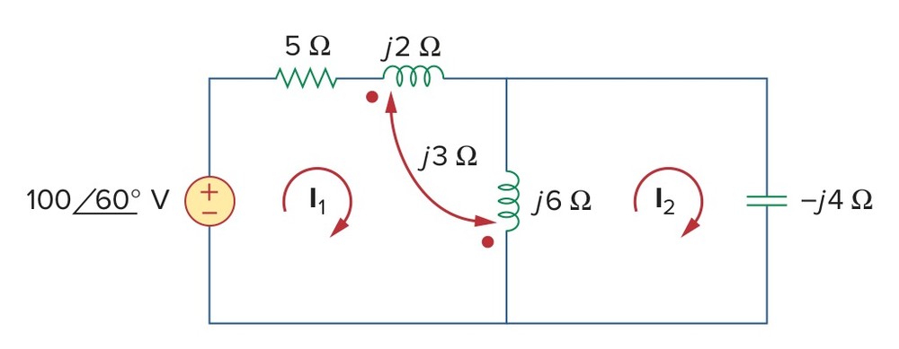
Alexander & Sadiku, 7th edition — the circuit for Practice Problem 13.2
Solution
The circuit consists of a source, a resistor, two coupled coils and a capacitor in two meshes, and the question wants the two mesh currents. Each mesh current is the current of an element that only its own mesh contains: \(I_1\) flows through the 5 Ω resistor and \(I_2\) down through the capacitor. The coils are given as reactances in ohms, so we write each as a resistor with an imaginary value, rl2 worth 2j and rl6 worth 6j, and the coupling between them as the m line, which names the two and their mutual reactance, 3j. The m line reads each coil's first node as its dotted end. The j2 Ω coil's dot is on the side of the 5 Ω, node 2, and the j6 Ω coil's dot is at the bottom, so we write them rl2,2,3,2j and rl6,0,3,6j. We call the node between the 5 Ω and the coil 2 and the top of the capacitor 3, with the bottom rail as ground, and name the capacitor rc.
e,1,0,(100∠60°)
r5,1,2,5
rl2,2,3,2j
m,rl2,rl6,3j
rl6,0,3,6j
rc,3,0,-4j
Set Analysis to AC — alternating current. Leave omega in the ω — angular frequency box, since nothing here depends on the frequency. Set Rounding in Settings to approx to n digits with n = 4.
Symbulator returns i_r5 = 1.072 + 17.86j A (17.89∠86.57°, the book's \(I_1\)) and i_rc = 1.608 + 26.78j A (26.83∠86.57°, the book's \(I_2\)).
AS7's Practice Problem 13.13
Open in app ↗Open in split view
Find \(i_o\) in the circuit of the figure.

Alexander & Sadiku, 7th edition — the circuit for Practice Problem 13.13
Solution
The circuit consists of a 160 V cosine source at 4 rad/s, two coils coupled with a coefficient of 0.4, a third coil, a capacitor and four resistors. The question wants the current \(i_o\) through the 8 Ω resistor. The coils and the capacitor are given in henries and farads, so we write them as they are and put 4 in the ω — angular frequency box. The source's value is the phasor (160∠50°). The coupling the figure gives as \(k\), and the m line takes it as it is, m,l1,l2,k=0.4, naming the two coils. The m line reads each coil's first node as its dotted end. The 5 H coil's dot is at its top and the 4 H coil's at its bottom, so we write them l1,a,m,5 and l2,m,b,4. The source's bottom and the left end of the 10 Ω are the bottom wire, which we take as ground. We call the top of the 5 H a, the middle wire the two coils and the capacitor share m, the top of the 4 H b, the top of the 6 H c and the right-hand node r. \(i_o\) flows leftward through the 8 Ω, from r to ground, which is how r8,r,0 counts it.
e,1,0,(160∠50°)
r20,1,a,20
l1,a,m,5
l2,m,b,4
m,l1,l2,k=0.4
r12,b,c,12
l3,c,r,6
c,m,r,25'm
r10,0,m,10
r8,r,0,8
Set Analysis to AC — alternating current. Put 4 in the ω — angular frequency box. Set Rounding in Settings to approx to n digits with n = 4.
Symbulator returns i_r8 = 0.7367 + 1.871j A (2.011∠68.51°, the book's \(I_o\)).
As a function of time that is \(i_o\) = 2.012 cos(4\(t\) + 68.52°) A.
AS7's Example 13.14
Open in app ↗Open in split view
Find \(V_1\) and \(V_2\) in the ideal transformer circuit of the figure.

Alexander & Sadiku, 7th edition — the circuit for Example 13.14
Solution
The circuit consists of a source feeding an ideal 4:1 transformer through an impedance, with a 20 Ω resistor below the two windings and a load on the secondary. The question wants the voltage across each winding. The two windings' lower ends meet at the top of the 20 Ω, so they share a node, which we call x. An ideal transformer is the element t, and when its windings share a node we write each winding as a bracketed pair of terminals, top node then bottom: [p,x] for the primary and [q,x] for the secondary, followed by the turns. The primary's dot is at its top and the secondary's at its bottom, and that polarity is a minus sign on one of the turn counts, so the ratio is [-4,1]. We call the source's top 1, the primary's top p and the secondary's top q. The 80 Ω and −j40 Ω are in series with nothing between them, so we write them as one impedance, r1 worth 80-40j, and likewise the 6 Ω and j10 Ω as r3.
e,1,0,(120∠30°)
r1,1,p,80-40j
t,[p,x],[q,x],[-4,1]
r2,x,0,20
r3,q,0,6+10j
Set Analysis to AC — alternating current. Leave omega in the ω — angular frequency box, since nothing here depends on the frequency. Set Rounding in Settings to approx to n digits with n = 4.
\(V_1\) is the voltage across the primary, from p to x. We type it into Evaluate:
v_p-v_xIt gives 71.96 + 55.85j V (91.09∠37.81°, the book's \(V_1\)).
And \(V_2\), across the secondary from q to x:
v_q-v_xIt gives -17.99 - 13.96j V (22.77∠-142.2°, the book's \(V_2\)).
AS7's Example 14.10
Open in app ↗Open in split view
(a) Determine what type of filter is shown in the figure. (b) Calculate the corner or cutoff frequency. Take \(R\) = 2 kΩ, \(L\) = 2 H, and \(C\) = 2 μF.

Alexander & Sadiku, 7th edition — the circuit for Example 14.10
Solution
The circuit consists of an inductor in series with a resistor and a capacitor in parallel, the output taken across the pair. The question wants the kind of filter it is and its corner frequency. Both are properties of its gain as a function of frequency, so we leave the input as the symbol vi and the frequency as the symbol omega, and every answer comes back as a formula in both. The inductor and the capacitor are given in henries and farads, so we write them as they are. We name the resistor rr, call the input node 1 and the output 2.
e,1,0,vi
l,1,2,2
rr,2,0,2'k
c,2,0,2'u
Set Analysis to AC — alternating current. Leave omega in the ω — angular frequency box, since nothing here depends on the frequency. Set Rounding in Settings to approx to n digits with n = 4.
(a) A filter's type is set by how its gain behaves at the two ends of the frequency range. The gain is the output over the input, and we type it into Evaluate with the frequency at zero in its Conditions box:
v_2/viomega = 0It gives 1 (the book's \(H(0)\)).
At the other end we ask for its limit as the frequency grows without bound:
limit(v_2/vi, omega, oo)It gives 0 (the book's \(H(\infty)\)).
The gain passes low frequencies and stops high ones, so this is a low-pass filter.
(b) Its corner frequency is where the magnitude of the gain has fallen to \(1/\sqrt{2}\) of its value at zero. In the Solve card that is one equation, with the frequency as the unknown:
abs(v_2/vi)=1/sqrt(2)omegaTick real solutions only and press Solve equations.
The card returns 2 solutions, omega = -742.3 and omega = 742.3.
AS7's Practice Problem 14.10
Open in app ↗Open in split view
For the circuit in the figure, (a) obtain the transfer function \(V_o(\omega)/V_i(\omega)\). (b) Identify the type of filter the circuit represents and (c) determine the corner frequency. Take \(R_1\) = 100 Ω = \(R_2\), \(L\) = 2 mH.

Alexander & Sadiku, 7th edition — the circuit for Practice Problem 14.10
Solution
The circuit consists of a resistor in series with an inductor and a second resistor in parallel, the output taken across the pair. The question wants the transfer function, the kind of filter and its corner frequency. We leave the input as the symbol vi and the frequency as the symbol omega, so every answer comes back as a formula in both, and we write the inductor as it is given, 2'm. We call the input node 1 and the output o, and name the resistors after the book's \(R_1\) and \(R_2\). The transfer function is the output voltage divided by vi, which we read in the Evaluate card.
e,1,0,vi
r1,1,o,100
l,o,0,2'm
r2,o,0,100
Set Analysis to AC — alternating current. Leave omega in the ω — angular frequency box, since nothing here depends on the frequency. Set Rounding in Settings to approx to n digits with n = 4.
(a) is the transfer function above.
(b) A filter's type is set by how its gain behaves at the two ends of the frequency range. We type the gain into Evaluate with the frequency at zero in its Conditions box:
v_o/viomega = 0It gives 0 (the book's \(H(0)\)).
At the other end we ask for its limit as the frequency grows without bound:
limit(v_o/vi, omega, oo)It gives 0.5 (the book's \(H(\infty)\)).
The gain stops low frequencies and passes high ones, so this is a high-pass filter.
(c) Its corner frequency is where the magnitude of the gain has fallen to \(1/\sqrt{2}\) of its high-frequency value, 1/2. In the Solve card that is one equation, with the frequency as the unknown:
abs(v_o/vi)=1/(2*sqrt(2))omegaTick real solutions only and press Solve equations.
The card returns 2 solutions, omega = -25000 and omega = 25000.
The positive root is the corner frequency, 25 krad/s.
The s domain — FD
Six problems are in the \(s\) domain. FD returns every answer as a function of \(s\), initial conditions included, so a transfer function is nothing more than an answer with the source left as a symbol. A question about time is worked the way the book works it: the circuit is solved in the \(s\) domain and the answer inverted afterwards, which is what s2t does in the Evaluate card. The initial- and final-value theorems are two limits typed into the same card, and poles and zeros are one entry in the Mini-Tools card.
AS7's Example 14.2
Open in app ↗Open in split view
For the circuit in the figure, calculate (a) the gain \(I_o(\omega)/I_i(\omega)\) and (b) its poles and zeros.

Alexander & Sadiku, 7th edition — the circuit for Example 14.2
Solution
The circuit consists of a current source feeding two branches in parallel, a 4 Ω resistor in series with a 2 H inductor, and a 0.5 F capacitor. The question wants the ratio of the capacitor's current to the source's, and its poles and zeros. Poles and zeros belong to a function of \(s\), so we set the analysis to FD, which writes the inductor as \(2s\) and the capacitor as \(1/0.5s\). We leave the source as the symbol ii, so that every answer comes back as a multiple of it, and write the capacitance as the fraction 1/2, which keeps the answers exact. We call the top node 1 and the node between the resistor and the inductor a. \(I_o\) flows down through the capacitor, which is how c,1,0 counts it, and the gain is its current divided by ii, which we will read in the Evaluate card.
j,0,1,ii
r4,1,a,4
l,a,0,2
c,1,0,1/2
Set Analysis to FD — complex frequency domain.
(a) is the current gain above.
(b) The poles are the values of \(s\) that make the gain's denominator zero, and the zeros the values that make its numerator zero. The Mini-Tools card finds both at once: we choose pz — poles and zeros in its Tool menu and give it the gain.
ic/iiPress Run.
The card returns the poles -1 ×2, and the zeros -2 and 0.
The mark ×2 says the pole is a double one. So the gain has zeros at \(s\) = 0 and \(s\) = −2 and a double pole at \(s\) = −1. The book writes the gain in \(\omega\), and \(s\) = \(j\omega\) turns one form into the other.
AS7's Example 16.4
Open in app ↗Open in split view
Consider the circuit in the figure. Find the value of the voltage across the capacitor assuming that the value of \(v_s(t)\) = \(10u(t)\) V and assume that at \(t\) = 0, −1 A flows through the inductor and +5 V is across the capacitor.

Alexander & Sadiku, 7th edition — the circuit for Example 16.4
Solution
The circuit consists of a step source feeding a resistor, and an inductor and a capacitor in parallel, each holding an initial condition. The question wants the capacitor's voltage, and the book's chapter works it by the Laplace method, so we set the analysis to FD. A 10 V step has the transform \(10/s\), which we write as the source's value, 10/s. We put the initial conditions in the fifth fields: −1 A on the inductor, counted downward from node 2 as l,2,0 counts it, and 5 V on the capacitor. We write the resistance and the capacitance as the fractions the book gives, 10/3 and 1/10. The capacitor's voltage is the voltage at node 2.
e,1,0,10/s
r,1,2,10/3
l,2,0,5,-1
c,2,0,1/10,5
Set Analysis to FD — complex frequency domain.
v_2 is the book's \(V_1(s)\).
The question asks for the voltage as a function of time. s2t turns a function of \(s\) back into a function of \(t\), so we give it the answer just read.
s2t(v_2)It gives:
AS7's Example 16.6
Open in app ↗Open in split view
Assume that there is no initial energy stored in the circuit of the figure at \(t\) = 0 and that \(i_s\) = \(10u(t)\) A. (a) Find \(V_o(s)\). (b) Apply the initial- and final-value theorems to find \(v_o(0^+)\) and \(v_o(\infty)\). (c) Determine \(v_o(t)\).
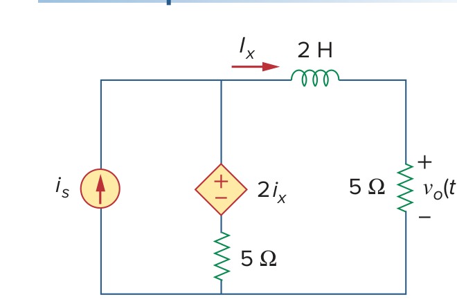
Alexander & Sadiku, 7th edition — the circuit for Example 16.6
Solution
The circuit consists of a step current source, a 2 H inductor, a dependent voltage source worth twice the inductor's current, and two 5 Ω resistors. The question wants the output voltage as a function of \(s\), its initial and final values, and the voltage as a function of time. We set the analysis to FD. A 10 A step has the transform \(10/s\), which we write as the source's value, j,0,a,10/s. We call the top left node a, the right end of the inductor b and the node between the dependent source and its 5 Ω m. \(I_x\) flows through the inductor from a to b, so it is il and the dependent source is e,a,m,2*il. We name the 5 Ω under the dependent source r5a and the output resistor r5b. \(V_o\) is the voltage at node b.
j,0,a,10/s
l,a,b,2
e,a,m,2*il
r5a,m,0,5
r5b,b,0,5
Set Analysis to FD — complex frequency domain. Set Rounding in Settings to approx to n digits with n = 4.
(a) is v_b (the book's \(V_o(s)\)).
(b) The initial-value theorem says \(v_o(0^+)\) is the limit of \(sV_o(s)\) as \(s\) grows without bound. We type that limit into Evaluate:
limit(s*v_b, s, oo)It gives 0 V (the book's \(v_o(0^+)\)).
The final-value theorem says \(v_o(\infty)\) is the same product's limit as \(s\) goes to zero:
limit(s*v_b, s, 0)It gives 31.25 V (the book's \(v_o(\infty)\)).
(c) s2t turns \(V_o(s)\) back into a function of time:
s2t(v_b)It gives:
AS7's Practice Problem 16.6
Open in app ↗Open in split view
The initial energy in the circuit of the figure is zero at \(t\) = 0. Assume that \(v_s\) = \(30u(t)\) V. (a) Find \(V_o(s)\). (b) Apply the initial- and final-value theorems to find \(v_o(0)\) and \(v_o(\infty)\). (c) Obtain \(v_o(t)\).
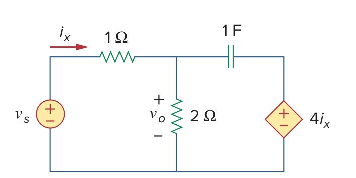
Alexander & Sadiku, 7th edition — the circuit for Practice Problem 16.6
Solution
The circuit consists of a step source, a 1 Ω resistor, a 2 Ω resistor, a 1 F capacitor and a dependent voltage source worth four times \(i_x\), the current through the 1 Ω. The question wants the output as a function of \(s\), its initial and final values, and the output as a function of time. We set the analysis to FD. A 30 V step has the transform \(30/s\), so the source is e1,1,0,30/s. We call the source's top 1, the top of the 2 Ω m and the top of the dependent source r, and name the resistors r1 and r2. \(i_x\) flows from node 1 to m through r1, so the dependent source is e2,r,0,4*ir1. \(V_o\) is the voltage at node m.
e1,1,0,30/s
r1,1,m,1
r2,m,0,2
c,m,r,1
e2,r,0,4*ir1
Set Analysis to FD — complex frequency domain.
(a) is v_m (the book's \(V_o(s)\)).
(b) The initial-value theorem gives \(v_o(0)\) as the limit of \(sV_o(s)\) as \(s\) grows without bound. We type that limit into Evaluate:
limit(s*v_m, s, oo)It gives 24 V (the book's \(v_o(0)\)).
The final-value theorem gives \(v_o(\infty)\) as the same product's limit as \(s\) goes to zero:
limit(s*v_m, s, 0)It gives 20 V (the book's \(v_o(\infty)\)).
(c) s2t turns \(V_o(s)\) back into a function of time:
s2t(v_m)It gives:
AS7's Example 16.8
Open in app ↗Open in split view
Determine the transfer function \(H(s)\) = \(V_o(s)/I_o(s)\) of the circuit in the figure. (Practice Problem 16.8 asks the same circuit for \(I_1(s)/I_o(s)\).)

Alexander & Sadiku, 7th edition — the circuit for Example 16.8
Solution
The circuit is given in the \(s\) domain: a source feeding a 1 Ω resistor, then two branches, an \(s\) Ω inductor in series with a 4 Ω resistor, and a \(1/2s\) Ω capacitor in series with a 2 Ω resistor. The question wants the ratio of the output voltage across the 2 Ω to the current into the circuit. We set the analysis to FD and write the elements by their values: an inductor of 1 H, whose impedance is \(s\), and a capacitor of 2 F, whose impedance is \(1/2s\). We leave the source as the symbol vs. \(I_o\) is the current through the 1 Ω, r1. We call the top node t, the node between the inductor and the 4 Ω m, and the top of the 2 Ω b, so \(V_o\) is the voltage at node b.
e,1,0,vs
r1,1,t,1
l,t,m,1
r4,m,0,4
c,t,b,2
r2,b,0,2
Set Analysis to FD — complex frequency domain.
The transfer function is the output voltage over the current into the circuit. We type that ratio into Evaluate:
v_b/i_r1It gives:
Practice Problem 16.8's ratio is the current down through the inductor branch over the same input current:
i_l/i_r1It gives:
AS7's Example 16.9
Open in app ↗Open in split view
For the s-domain circuit in the figure, find: (a) the transfer function \(H(s)\) = \(V_o/V_i\), (b) the impulse response, (c) the response when \(v_i(t)\) = \(u(t)\) V, (d) the response when \(v_i(t)\) = 8 cos 2\(t\) V.

Alexander & Sadiku, 7th edition — the circuit for Example 16.9
Solution
The circuit is given in the \(s\) domain: three 1 Ω resistors and an inductor whose impedance is \(s\), that is 1 H. The question wants the transfer function and the circuit's response to three different inputs. One FD run gives the transfer function, and each response is that function times the input's transform, turned back into time. So we leave the input as the symbol vi and set the analysis to FD. We call the input node in, keep the figure's a, and call the output out.
e,in,0,vi
r1,in,a,1
r2,a,0,1
l,a,out,1
r3,out,0,1
Set Analysis to FD — complex frequency domain. Set Rounding in Settings to approx to n digits with n = 4.
(a) The transfer function is the output over the input. We type that ratio into Evaluate:
v_out/viIt gives:
(b) The impulse response is the output when the input's transform is 1, which is \(H(s)\) itself back in the time domain. s2t does that:
s2t(v_out/vi)It gives:
(c) A unit step has the transform \(1/s\), so the step response is \(H(s)/s\) back in the time domain:
s2t(v_out/vi/s)It gives:
(d) The transform of 8 cos 2\(t\) is \(8s/(s^2+4)\), and the response is \(H(s)\) times that, back in the time domain:
s2t(v_out/vi*8*s/(s^2+4))It gives: